FUEL TANK REMOVAL/INSTALLATION [MZR-CD (RF Turbo)]
FUEL TANK REMOVAL/INSTALLATION [MZR-CD (RF Turbo)]
id0114f1801600
-
Warning
-
• Repairing a fuel tank that has not been properly steam cleaned can be dangerous. Explosion or fire may cause death or serious injury. Always properly steam clean a fuel tank before repairing it.
-
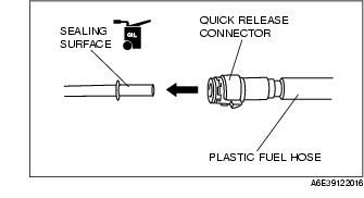
• Fuel line spills and leakage are dangerous. Fuel can also irritate skin and eyes. To prevent this, do not damage the sealing surface of the fuel gauge sender unit when removing or installing.
-
• A person charged with static electricity could cause a fire or explosion, resulting in death or serious injury. Before draining fuel, make sure to discharge static electricity by touching the vehicle body.
-
Caution
-
• Disconnecting/connecting the quick release connector without cleaning it may possibly cause damage to the fuel pipe and quick release connector. Always clean the quick release connector joint area before disconnecting/connecting using a cloth or soft brush, and make sure that it is free of foreign material.
1. Verify that vehicle is level.
2. Complete the "BEFORE REPAIR PROCEDURE". (See BEFORE REPAIR PROCEDURE [MZR-CD (RF Turbo)].)
3. Disconnect the negative battery cable.
4. Remove the rear seat cushion. (See REAR SEAT REMOVAL/INSTALLATION [EXCEPT WGN (4WD)].) (See REAR SEAT REMOVAL/INSTALLATION [WGN (4WD)].)
5. Remove the service hole cover.
6. Remove the plastic fuel hose from the fuel gauge sender unit. (See Plastic Fuel Hose Removal Note.) (See Plastic Fuel Hose Installation Note.)
7. Remove the fuel gauge sender unit connector.
8. Remove the fuel tank gauge cap. (See Fuel Tank Gauge Cap Removal Note.)
9. Remove the fuel gauge sender unit. (See Fuel Gauge Sender Unit Installation Note.)
10. Siphon the fuel from the fuel tank.
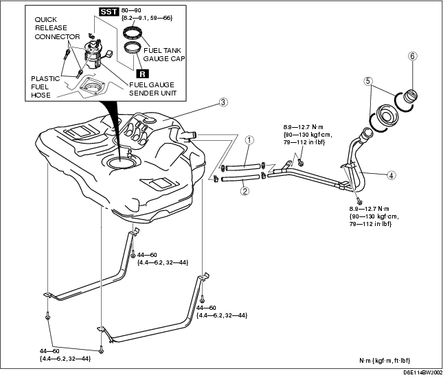
11. Remove in the order indicated in the table.
12. Install in the reverse order of removal.
13. Complete the "AFTER REPAIR PROCEDURE". (See AFTER REPAIR PROCEDURE [MZR-CD (RF Turbo)].)
.
|
1
|
Joint hose
|
|
2
|
Breather hose
|
|
3
|
Fuel tank
|
|
4
|
Fuel-filler pipe
|
|
5
|
C-ring
|
|
6
|
Filler cap
|
Plastic Fuel Hose Removal Note
-
Caution
-
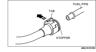
• The quick release connector may be damaged if the tab is bent excessively. Do not expand the tab over the stopper.
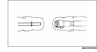
1. Disconnect the quick release connector.
-
(1) Push the tab on the locking coupler 90 degrees until it stops.
-
(2) Pull the fuel hose straight back.
-
Note
-
• The stopper may be removed from the quick release connector. Take care not to lose it.
-
Reinstall it to the quick release connector before reconnecting the fuel line.
-
• The locking coupler has two internal locking tabs which retain the fuel pipe. Be sure that the tab on the locking coupler is rotated until it stops to release two internal locking tabs.

2. Cover the disconnected quick release connector and fuel pipe with vinyl sheets or the like to prevent them from being scratched or contaminated with foreign material.
Fuel Tank Gauge Cap Removal Note
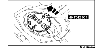
1. Using the SST, remove the fuel tank gauge cap.
Breather Hose Installation Note
1. Fit the breather hose onto the respective fittings, and install clamps as shown.
Joint Hose Installation Note
1. Fit the joint hose onto the respective fittings, and install clamps as shown.
Fuel Gauge Sender Unit Installation Note
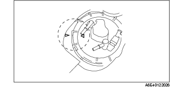
1. Verify that the fuel tank mark is aligned with the fuel gauge sender unit mark as shown.
Plastic Fuel Hose Installation Note
-
Note
-
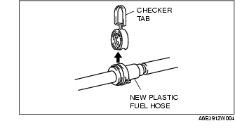
• A checker tab is integrated with quick release connector for new plastic fuel hoses. The checker tab will be released from the quick release connector after it is completely engaged with the fuel pipe.
1. Inspect the fuel gauge sender unit sealing surface for damage and deformation, and replace as necessary.
-
• If the quick release connector O-ring is damaged, replace the plastic fuel hose.
2. Apply a slight amount of clean engine oil to the sealing surface of the fuel gauge sender unit.
-
Note
-
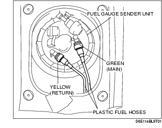
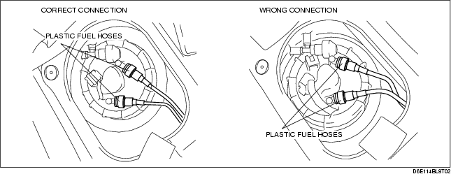
• The color of the quick release connector retainer for the plastic fuel hose is different on the main and return side to prevent miss-assembly. Connect the plastic fuel hoses as shown in the figure.
-
• If it is difficult to identify the quick release connectors by the retainer colors, connect the main side and return side plastic fuel hoses in the correct layout shown in the figure.
3. Align the fuel pipe on the fuel gauge sender unit and quick release connector so that the tabs of the retainer are correctly fitted into the quick release connector. Push the quick release connector straight into the retainer until a click is heard.
4. Lightly pull and push the quick release connector a few times by hand and verify that it can move 2.0-3.0 mm {0.08-0.11 in} and it is connected securely.
-
• If the quick release connector does not move at all, verify that O-ring is not damaged of that is has not slipped, and reconnect the quick release connector.