 |
am6zzw00007408
SUPPLY PUMP REMOVAL/INSTALLATION [MZR-CD (RF Turbo)]
id0114f1805700
|
STEP |
ACTION |
PAGE/CONDITION |
|---|---|---|
|
1
|
Replace the supply pump.
|
–
|
|
2
|
Turn the engine switch on.
|
–
|
|
3
|
Perform supply pump data reset procedure.
|
Engine coolant temperature 60—100 °C {140—212 °F}
|
|
4
|
Start the engine.
|
Verify that the MIL does not illuminate.
|
|
5
|
Turn the engine switch off.
|
–
|
|
6
|
Turn the engine switch on (Engine off).
|
–
|
|
7
|
Perform KOEO self-test procedure.
|
|
|
8
|
Turn the engine switch off.
|
–
|
|
9
|
Wait for 20 s.
|
–
|
|
10
|
Start the engine.
|
–
|
|
11
|
Perform KOER self-test procedure.
|
Warm up until the exhaust gas temperature (EXHTEMP1, EXHTEMP2, EXHTEMP3 PID) is 100 °C {212 °F} or more.
|
|
12
|
Turn the engine switch off.
|
–
|
1. Disconnect the negative battery cable.
2. Remove the under cover and splash shield.
3. Remove the dipstick pipe.
4. Remove the No.3 engine mount. (See TIMING BELT REMOVAL/INSTALLATION [MZR-CD (RF Turbo)].)
5. Remove the upper timing belt cover.
6. Complete the “BEFORE SERVICE PRECAUTION”. (See BEFORE SERVICE PRECAUTION [MZR-CD (RF Turbo)].)
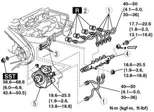
7. Remove in the order indicated in the table.
am6zzw00007408
|
|
1
|
Injection pipe
|
|
2
|
Nozzle seal
|
|
3
|
Fuel hose
|
|
4
|
Common rail
|
|
5
|
Supply pump
(See Supply Pump Removal Note.)
|
8. Install in the reverse order of removal.
9. Complete the “AFTER SERVICE PRECAUTION”. (See AFTER SERVICE PRECAUTION [MZR-CD (RF Turbo)].)
Supply Pump Removal Note
1. Verify that timing marks are correctly aligned.
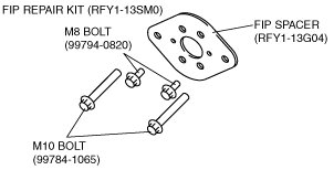
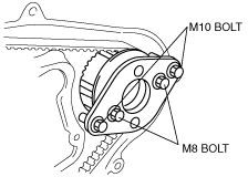
2. Lock the supply pump pulley against rotation using the FIP repair kit (RFY1-13SM0).
am5ezw00002237
|
am5ezw00002231
|
3. Remove the supply pump pulley lock nut.
4. Remove the supply pump lock nut.
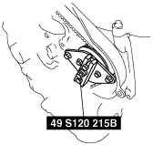
5. Separate the supply pump pulley from the supply pump shaft using the SST.
am5ezw00002232
|
6. Remove the SST.
Supply Pump Installation Note
1. Lock the supply pump pulley against rotation using the FIP repair kit (RFY1-13SM0).
am5ezw00002237
|
am5ezw00002231
|
2. Install the supply pump lock nut.
3. Install the supply pump pulley lock nut.
4. Remove the FIP repair kit.
5. Rotate the crankshaft clockwise 2—3 turns and align the timing marks.
6. Verify that timing marks are correctly aligned.
Common Rail Installation Note
1. Temporarily tighten the common rail.
2. Temporarily tighten the injection pipes.
3. Fully tighten the injector side injection pipes, then tighten the common rail side.
4. Fully tighten the supply pump side and common rail side injection pipes.
5. Fully tighten the common rail.
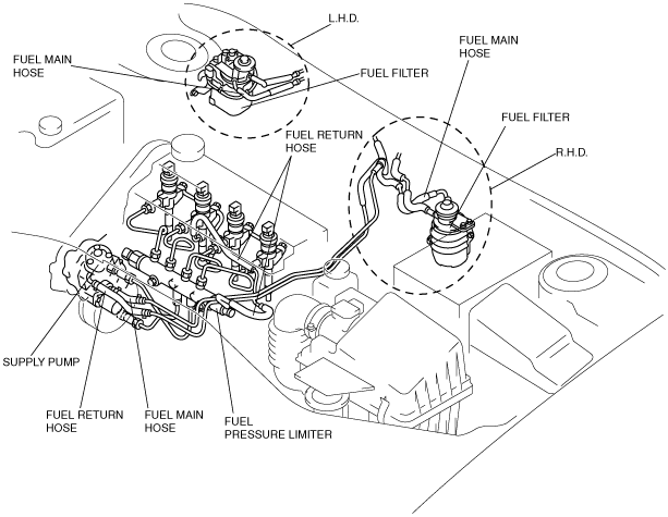
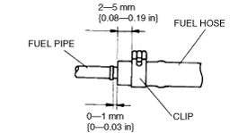
Fuel Hose Installation Note
1. Install the fuel main hose and fuel return hose as shown in the figure.
am6zzw00004716
|
2. Fit the fuel pipe onto the respective fittings, and install clamps as shown.
am6zzw00004717
|