1. Remove in the order indicated in the table.
2. Install in the reverse order of removal.
.
|
1
|
Main silencer
|
|
2
|
Presilencer
|
|
3
|
TWC
(See TWC Installation Note.)
|
|
4
|
Seal ring
(See Seal Ring Removal Note.)
(See Seal Ring Installation Note.)
|
|
5
|
Exhaust manifold insulator (upper)
|
|
6
|
Bracket
(See Bracket Installation Note.)
|
|
7
|
Exhaust manifold
|
|
8
|
Exhaust manifold gasket
|
|
9
|
Exhaust manifold insulator (lower)
|
|
10
|
A/F sensor
|
|
11
|
HO2S
|
1. Remove the seal ring using a flathead screwdriver being careful not to damage the pipe.
1. Using the SST, remove the A/F Sensor, HO2S.
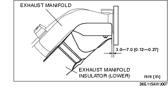
1. Tighten the exhaust manifold insulator (lower) installation bolts in the order shown.
2. Verify that there is 3.0-7.0 mm {0.12-0.27 in} gap between the exhaust manifold and the exhaust manifold insulator (lower).
1. Tighten the exhaust manifold installation nuts in the order shown.
1. Temporarily tighten the bracket installation bolt by the side of the exhaust manifold.
2. Verify that there is 2.0-4.0 mm {0.08-0.15 in} gap between the exhaust manifold and the bracket.
3. Tighten the bracket installation bolt by the side of the cylinder block.
Tightening torque4. Tighten the bracket installation bolt by the side of the exhaust manifold.
Tightening torque1. Tighten the exhaust manifold insulator (upper) installation bolts in the order shown.
1. Temporarily install the seal ring to the pipe so that the seal ring is even with the flange.
2. Install the SST to the seal ring so that the SST is even with the flange.
3. Press in the seal ring by tapping the SST using a plastic hammer until the seal ring contacts the flange.
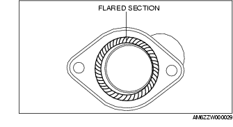
1. Spray carbon remover (TB6601 or equivalent) on the flared section of the exhaust pipe.
2. Remove the carbon adhering to the flared section shown in the figure using a nylon brush or sandpaper (No. 400 or equivalent).