 |
am6zzw00007994
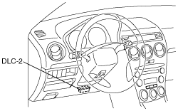
PCM INSPECTION [L3 Turbo]
id0140b6802500
Using the WDS or Equivalent
1. Connect the WDS or equivalent to the DLC-2.
am6zzw00007994
|
2. Turn the ignition switch to the ON position.
3. Measure the PID value.
PID/DATA monitor table (reference)
|
Monitor item (Definition) |
Unit/Condition |
Condition/Specification (Reference) |
Inspection item |
PCM terminal |
|
|---|---|---|---|---|---|
|
AC_REQ (A/C switch)
|
On/Off
|
A/C switch and fan switch ON at ignition switch ON: On
A/C switch OFF at ignition switch ON: Off
|
• A/C switch
|
1AC
|
|
|
ACCS (A/C relay)
|
On/Off
|
Ignition switch ON: Off
A/C switch ON and fan switch ON at idle: On
|
• The following PIDs:
• A/C relay
|
4N
|
|
|
ALTF (Generator field coil control duty value)
|
%
|
Ignition switch ON: 0%
Idle: 0—100%
Just after A/C switch ON and fan switch ON at idle: Duty value rises
|
• The following PIDs:
• Generator
|
1AD
|
|
|
ALTT V (Generator output voltage)
|
V
|
Ignition switch ON: 0 V
Idle: Approx. 14.5 V*1 (E/L not operating)
|
• Generator
|
1AB
|
|
|
AFR
|
—
|
Target air-oil ratio is displayed
|
• A/F sensor
|
1Y
2D
2G
2J
|
|
|
AFR_ACT
|
—
|
Actual air-oil ratio is displayed
|
• A/F sensor
|
1Y
2D
2G
2J
|
|
|
APP (Accelerator pedal position)
|
%
|
AP is released: 0%
AP is depressed: 100%
|
• The following PIDs:
• Accelerator pedal position sensor
|
2A
3D
|
|
|
APP1 (Accelerator pedal position)
|
%
|
AP is released: 31.0—32.4%
AP is depressed: 69.8—81.8%
|
• Accelerator pedal position sensor
|
3D
|
|
|
V
|
AP is released: Approx. 1.6 V
AP is depressed: Approx. 3.9 V
|
||||
|
APP2 (Accelerator pedal position)
|
%
|
AP is released: 20.2—21.4%
AP is depressed: 58.8—70.8%
|
• Accelerator pedal position sensor
|
2A
|
|
|
V
|
AP is released: Approx. 1.0 V
AP is depressed: Approx. 3.4 V
|
||||
|
ARPMDES (Target engine speed)
|
RPM
|
No load: 700 rpm
E/L operating: 700 rpm
P/S operating: 700 rpm
A/C ON: 750 rpm
|
• The following PIDs:
• CKP sensor
|
—
|
|
|
B+ (Battery positive voltage)*4
|
V
|
Ignition switch ON: B+
|
• Main relay
• Battery
|
2Y
|
|
|
BARO (Barometric pressure)
|
Pa
|
Ignition switch ON: Indicate the atmospheric pressure
|
• BARO sensor
|
—
|
|
|
V
|
|||||
|
BAT
|
°C
|
Boost air temperature is displayed
|
• MAP/boost air temperature sensor
|
1S
|
|
|
BAT_V
|
V
|
Boost air temperature 20 °C {68 °F}: 2.4—2.6 V
|
• MAP/boost air temperature sensor
|
1S
|
|
|
Boost air temperature 30 °C {86 °F}: 1.7—1.9 V
|
|||||
|
BOO (Brake switch)
|
On/Off
|
Brake pedal depressed: On
Brake pedal released: Off
|
• Brake switch
|
1K
3T
|
|
|
BPA (Brake pressure applied switch)*5
|
On/Off
|
Brake pedal depressed: On
Brake pedal released: Off
|
• Brake switch
|
1K
3T
|
|
|
CATT11_DSD (Estimated catalytic converter temperature)
|
°C
|
°F
|
Indicate the estimated catalytic converter temperature
|
• Perform applicable DTC troubleshooting.
|
—
|
|
CHRGLP (Generator warning light)
|
On/Off
|
Ignition switch ON: On
Idle: Off
|
• Perform applicable DTC troubleshooting.
|
—
|
|
|
COLP (Refrigerant pressure switch (middle))
|
ON/OFF
|
Refrigerant pressure switch (middle) ON*2 at idle: ON
Refrigerant pressure switch (middle) OFF*3 at idle: OFF
|
• Refrigerant pressure switch
|
1Q
|
|
|
CPP (Clutch pedal position)
|
On/Off
|
Clutch pedal depressed: On
Clutch pedal released: Off
|
• CPP switch
|
1H
|
|
|
CPP/PNP (Shift lever position)
|
Drive/Neutral
|
Neutral position: Neutral
Others: Drive
|
• Neutral switch
|
1W
|
|
|
DTCCNT (Number of DTC detected)
|
—
|
—
|
• Perform applicable DTC troubleshooting.
|
—
|
|
|
ECT (Engine coolant temperature)
|
°C
|
°F
|
Ignition switch at ON position: Indicate the ECT
|
• ECT sensor
|
1M
|
|
V
|
ECT 20 °C {68 °F}: 3.04—3.14 V
ECT 60 °C {140 °F}: 1.29—1.39 V
|
||||
|
EQ_RAT11 (Equivalence ratio (lambda))
|
—
|
Idling after warm-up: Approx. 1
|
• Perform applicable DTC troubleshooting.
|
2D
2G
2J
|
|
|
EQ_RAT11_DSD
(A/F sensor)
|
—
|
Idling after warm-up: Approx. 1
|
• Perform applicable DTC troubleshooting.
|
2D
2G
2J
|
|
|
ETC_ACT (Electronic throttle control actual)
|
°
|
Indicate the desired TP by angle
|
• Perform applicable DTC troubleshooting.
|
3J
3M
|
|
|
ETC_DSD (Electronic throttle control desired)
|
%
|
Indicate the desired TP by percent
|
• The following PIDs:
• TP sensor
|
3J
3M
|
|
|
°
|
Indicate the desired TP by angle
|
||||
|
EVAPCP (Purge solenoid valve duty value)
|
%
|
Ignition switch ON: 0%
Idle: 0%
|
• The following PIDs:
• Purge solenoid valve
|
4T
|
|
|
FAN_DUTY
|
%
|
ECT less than 98 °C {208 °F}: 0%
ECT 100 °C {212 °F}: 30%
ECT 106 °C {223 °F}: 70%
ECT 110 °C {230 °F}: 100%
|
• Fan control module
|
4A
|
|
|
FIA (Fuel injection amount)
|
mg/cylinder
|
Indicate the fuel injection amount
|
• Fuel injector
• Injector driver module
|
—
|
|
|
FP (Fuel pump relay)
|
On/Off
|
Idle: On
Cranking: On
|
• The following PIDs:
• Fuel pump relay
|
4Q
|
|
|
FP_Hi_PRES
|
On/Off
|
Spill valve control solenoid valve work: On
Spill valve control solenoid valve don’t work: Off
|
• High pressure fuel pump
|
1A
1B
|
|
|
FUEL_PRES
|
Pa
|
Idle: Approx. 3 MPa
Load 60 % or more: Approx. 11.5 MPa
|
• Fuel pressure sensor
|
1V
|
|
|
FUEL_PRES_V
|
V
|
Idle: Approx. 1.4 V
|
• Fuel pressure sensor
|
1V
|
|
|
FUELSYS (Fuel system status)
|
OL/CL/
OL-Drive/
OL-Fault/
CL-Fault
|
Ignition switch ON: OL_Drive
Idle (after warm up): CL
|
• The following PIDs:
• Fuel injector
|
—
|
|
|
GENVDSD (Generator voltage desired)
|
V
|
Idle: Approx. 13.83 V*1 (E/L not operating)
|
• Perform applicable DTC troubleshooting.
|
—
|
|
|
HTR11 (A/F sensor heater)
|
On/Off
|
Idle (after warm up): OnÛOff
|
• The following PIDs:
|
4AD
|
|
|
HTR12 (HO2S heater)
|
On/Off
|
Idle: On
Engine speed is above 4,000 rpm: Off
|
• The following PIDs:
|
4Z
|
|
|
IAT (Intake air temperature)
|
°C
|
°F
|
Ignition switch at ON position: Indicate the IAT
|
• IAT sensor
|
2V
|
|
V
|
IAT 20 °C {68 °F}: 2.4—2.6V
IAT 30 °C {86 °F}: 1.7—1.9V
|
||||
|
IMRC (Variable swirl solenoid valve)
|
On/Off
|
Engine speed is less than 3,250 rpm and ECT is less than 60 °C {140 °F}: On
Engine speed is 3,250 rpm or more, or ECT is 60 °C {140 °F} or more: Off
|
• The following PIDs:
• Variable swirl solenoid valve
|
4K
|
|
|
INGEAR (Load/no load condition)
|
On/Off
|
CPP or CPP/PNP is On: Off
Others: On
|
• Perform applicable DTC troubleshooting.
|
1H
1W
|
|
|
IVS (CTP condition)
|
Idle/
Off Idle
|
APP closed: Idle
Others: Off Idle
|
• Perform applicable DTC troubleshooting.
|
3J
3M
|
|
|
KNOCKR (Knocking retard)
|
°
|
Ignition switch ON: 0 °
Idle: 0 °
|
• Knock sensor
|
2P
2S
|
|
|
LOAD (Engine load)
|
%
|
Ignition switch ON: 0%
Idle (after warm up): 17.1—18.5%
Engine speed is 2,500 rpm: 14.2—15.2
|
• MAF sensor
|
—
|
|
|
LONGFT1 (long term fuel trim)
|
%
|
Idle (after warm up):–14—14%
|
• Perform applicable DTC troubleshooting.
|
—
|
|
|
MAF (Mass airflow)
|
g/sec
|
Ignition switch ON: Approx. 0 g/s
Idle (after warm up): 2.72—2.94 g/s
Engine speed is 2,500 rpm: 8.00—8.66
|
• MAF sensor
|
1P
|
|
|
V
|
Ignition switch ON: Approx. 0.7 V
Idle (after warm up): 1.15—1.28 V
|
||||
|
MAP (Manifold absolute pressure)
|
Pa
|
Ignition switch at ON position: Indicate the atmospheric pressure
|
• MAP sensor
|
1J
|
|
|
V
|
Ignition switch ON
Manifold absolute pressure Approx. 102 kPa: Approx. 1.9 V
|
||||
|
Idle
Manifold absolute pressure Approx. 30 kPa: Approx. 0.7 V
|
|||||
|
MIL (Malfunction indicator lamp)
|
On/Off
|
Ignition switch ON: On
Idle: Off
|
• Perform applicable DTC troubleshooting.
|
—
|
|
|
MIL_DIS (Traveled distance since the MIL illuminated)
|
km
|
mile
|
No DTC: 0 km {0 mile}
DTC detected: Not 0 km {0 mile}
|
• Perform applicable DTC troubleshooting.
|
—
|
|
NUMKEYS (Number of keys stored in module)
|
—
|
Indicate the number of keys stored in module
|
—
|
—
|
|
|
O2S11 (A/F sensor)
|
A
|
Idle (after warm up): –1.0—1.0 A
Deceleration (after warm up):
0.25 A or more
|
• A/F sensor
|
2D
2G
2J
|
|
|
O2S12 (HO2S)
|
V
|
Idle (after warm up): 0—1.0 V
Acceleration (after warm up):
0.5—1.0 V
Deceleration (after warm up):
0—0.5 V
|
• HO2S
|
1Y
|
|
|
PSP (Power steering pressure switch)
|
High/Low
|
Steering wheel in straight ahead position: Low
Others: High
|
• PSP switch
|
1Z
|
|
|
RFCFLAG (Readness function code)
|
Learnt/ Not Learnt
|
Before running PCM adaptive memory procedure drive mode: Not Learnt
After running PCM adaptive memory procedure drive mode: Learnt
|
• Run PCM adaptive memory procedure drive mode.
|
—
|
|
|
RO2FT1 (HO2S fuel trim)
|
—
|
• Idle after warm-up: Approx. 0.2
|
• The following PID
|
1Y
|
|
|
RPM (Engine speed)
|
RPM
|
No load: 650—750 rpm
E/L operating: 650—750 rpm
P/S operating: 650—750 rpm
A/C ON: 700—800 rpm
|
• CKP sensor
|
2C
|
|
|
SCCS (Speed control command switch)
|
V
|
Press ON/OFF: Approx. 0 V
Press CANCEL: Approx. 1.2 V
Press SET/COAST: Approx. 3.2 V
Press RES/ACCEL: Approx. 4.2 V
Others: Approx. 5.0 V
|
• Cruise control switch
|
—
|
|
|
SEGRP (EGR valve (stepping motor) position)
|
—
|
Idle: 0 step
Cranking: 0—60 steps
|
• The following PIDs:
• EGR valve
|
—
|
|
|
SEGRP DSD (Desired EGR valve (stepping motor) position)
|
%
|
Idle: 0%
|
• The following PIDs:
|
—
|
|
|
SELTESTDTC
(DTC of KOEO/KOER self-test)
|
—
|
—
|
• Perform applicable DTC troubleshooting.
|
—
|
|
|
SHRTFT1 (Short term fuel trim [A/F sensor])
|
%
|
Idle (after warm up): Approx.–30—25%
|
• Perform applicable DTC troubleshooting.
|
—
|
|
|
SHRTFT12 (Short term fuel trim)
|
%
|
Idle (after warm up): Approx.–30—25%
|
• Perform applicable DTC troubleshooting.
|
—
|
|
|
SPARKADV (Ignition timing)
|
°(BTDC)
|
Idle: BTDC Approx. 8°
|
• The following PIDs:
• Ignition timing
|
—
|
|
|
test (Test mode)
|
On/Off
|
—
|
—
|
—
|
|
|
TIRESIZE (Tire revolution per mile)
|
rev/mile
|
Indicate the tire circumference length
|
—
|
—
|
|
|
TP REL (Relative TP)
|
%
|
Ignition switch to the ON position
• APP is released: Approx. 17%
Idle (after warm up)
• Gradually depress the accelerator pedal while verifying that the value changes.
|
• TP sensor
|
3J
3M
|
|
|
TP1 (TP sensor 1)
|
%
|
Ignition switch to the ON position
• APP is released: Approx. 17%
Idle (after warm up)
• Gradually depress the accelerator pedal while verifying that the value changes.
|
• TP sensor
|
3M
|
|
|
V
|
Ignition switch to the ON position
• APP is released: Approx. 0.85 V
Idle (after warm up)
• Gradually depress the accelerator pedal while verifying that the voltage changes.
|
||||
|
TP2 (TP sensor 2)
|
%
|
Ignition switch to the ON position
• APP is released: Approx. 17%
Idle (after warm up)
• Gradually depress the accelerator pedal while verifying that the value changes.
|
• TP sensor
|
3J
|
|
|
V
|
Ignition switch to the ON position
• APP is released: Approx. 4.11 V
Idle (after warm up)
• Gradually depress the accelerator pedal while verifying that the voltage changes.
|
||||
|
TPCT (Lowest closed throttle voltage)
|
V
|
Indicate the voltage of the closed TP sensor
|
• TP sensor
|
3J
3M
|
|
|
VPWR (Module supply voltage)*5
|
V
|
Indicate the Module supply voltage.
|
Inspect battery.
|
—
|
|
|
VSS (Vehicle speed)
|
KPH
|
MPH
|
Indicate the vehicle speed
|
• Perform applicable DTC troubleshooting.
|
—
|
|
VT ACT1 (Actual valve timing)
|
°
|
Idle: Approx. 0°
|
• The following PIDs:
• OCV
|
—
|
|
|
VT DIFF1 (Difference between actual valve timing and target valve timing)
|
°
|
Idle: Approx. 0°
|
• The following PIDs:
• OCV
|
4S
|
|
|
VT DUTY1
|
%
|
Idle: Approx. 11.5%
|
• The following PIDs:
• OCV
|
4S
|
|
|
WGC
|
%
|
Racing with the accelerator pedal fully depressed: 100 %
|
• Wastegate control solenoid valve
|
4H
|
|
|
Fully closed: 0 %
|
|||||
Without Using the SST
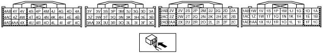
1. Measure the voltage at each terminal.
Terminal voltage table (Reference)
am6zzw00007995
|
|
Terminal |
Signal |
Connected to |
Test condition |
Voltage (V) |
Inspection item |
|
|---|---|---|---|---|---|---|
|
1A
|
High pressure fuel pump control (+)
|
High pressure fuel pump
|
Ignition switch OFF
|
Approx. 10.0
|
• High pressure fuel pump
• Related wiring harness Related wiring harness
|
|
|
Ignition switch ON
|
Approx. 9.6
|
|||||
|
Idle
|
Approx. 9.4
|
|||||
|
1B
|
High pressure fuel pump control (–)
|
High pressure fuel pump
|
Ignition switch OFF
|
Approx. 9.9
|
• High pressure fuel pump
• Related wiring harness Related wiring harness
|
|
|
Ignition switch ON
|
Approx. 9.7
|
|||||
|
Idle
|
Approx. 9.1
|
|||||
|
1C
|
GND
|
Body ground
|
Under any condition
|
Below 1.0
|
• Related wiring harness
|
|
|
1D
|
Variable swirl solenoid valve power supply
|
Main relay
|
Ignition switch OFF after 90s
|
Bellow 1.0
|
• Main relay
• Related wiring harness
|
|
|
Ignition switch ON
|
B+
|
|||||
|
1E
|
—
|
—
|
—
|
—
|
—
|
|
|
1F
|
—
|
—
|
—
|
—
|
—
|
|
|
1G
|
—
|
—
|
—
|
—
|
—
|
|
|
1H
|
Clutch operation
|
Clutch switch
|
Clutch pedal depressed
|
Below 1.0
|
• Clutch switch
• Related wiring harness
|
|
|
Clutch pedal released
|
B+
|
|||||
|
1I
|
MAF sensor GND
|
MAF/IAT sensor
|
Under any condition
|
Below 1.0
|
• MAF/IAT sensor
• Related wiring harness
|
|
|
1J
|
Manifold absolute pressure
|
MAP sensor
|
Ignition switch ON (Engine off) at sea level
|
Approx. 1.9
|
• MAP sensor
• Related wiring harness
|
|
|
Idle
|
Approx. 0.7
|
|||||
|
1K
|
Brake (No. 1)
|
Brake switch No. 1
|
Brake pedal depressed
|
B+
|
• Brake switch
• Related wiring harness
|
|
|
Brake pedal released
|
Below 1.0
|
|||||
|
1L
|
—
|
—
|
—
|
—
|
—
|
|
|
1M
|
ECT
|
ECT sensor
|
Ignition switch ON
|
ECT 20 °C
{68 °F}
|
3.04—3.14
|
• ECT sensor
• Related wiring harness
|
|
ECT 60 °C
{140 °F}
|
1.29—1.39
|
|||||
|
1N
|
Variable swirl shutter valve monitor
|
Variable swirl shutter valve switch
|
Engine speed is less than 3,250 rpm and ECT is less than 60°C {140 °F}
|
Below 1.0
|
• Variable swirl shutter valve switch
• Related wiring harness
|
|
|
Engine speed is 3,250 rpm or more, or ECT is 60°C {140 °F} or more
|
Approx. 5.0
|
|||||
|
1O
|
—
|
—
|
—
|
—
|
—
|
|
|
1P
|
MAF
|
MAF sensor
|
Ignition switch ON
|
Approx. 0.7
|
• MAF sensor
• Related wiring harness
|
|
|
Idle (after warm up)
|
1.15—1.28
|
|||||
|
1Q
|
A/C compressor load
|
Refrigerant pressure switch (middle)
|
A/C ON
|
Refrigerant pressure is above 1.52 MPa {15.5 kgf/cm2, 220 psi}
|
Below 1.0
|
• Refrigerant pressure switch
• Related wiring harness
|
|
Refrigerant pressure is below 1.23 MPa {12.5 kgf/cm2, 178 psi}
|
B+
|
|||||
|
1R
|
—
|
—
|
—
|
—
|
—
|
|
|
1S
|
Boost air temperature
|
MAP/Boost air temperature sensor
|
Ignition switch ON
|
IAT 20 °C
{68 °F}
|
2.4—2.6
|
• Boost air temperature sensor
• Related wiring harness
|
|
IAT 30 °C
{86 °F}
|
1.7—1.9
|
|||||
|
1T
|
—
|
—
|
—
|
—
|
—
|
|
|
1U
|
—
|
—
|
—
|
—
|
—
|
|
|
1V
|
Fuel pressure sensor
|
Fuel pressure sensor
|
Ignition switch OFF
|
Approx. 1.4
|
• Fuel pressure sensor
• Related wiring harness
|
|
|
Ignition switch ON
|
Approx. 1.5
|
|||||
|
Idle
|
Approx. 1.4
|
|||||
|
1W
|
Neutral position
|
Neutral switch
|
Shift lever is at neutral position
|
Below 1.0
|
• Neutral switch
• Related wiring harness
|
|
|
Shift lever is not at neutral position
|
B+
|
|||||
|
1X
|
—
|
—
|
—
|
—
|
—
|
|
|
1Y
|
HO2S
|
HO2S
|
Ignition switch ON
|
Below 1.0
|
• HO2S
• Related wiring harness
|
|
|
Voltage changes between 0 and 1 according to the amount of racing
|
||||||
|
1Z
|
PSP
|
PSP switch
|
Idle
|
Steering wheel at straight ahead position
|
B+
|
• PSP switch
• Power steering system
• Related wiring harness
|
|
While turning steering wheel
|
Below 1.0
|
|||||
|
1AA
|
—
|
—
|
—
|
—
|
—
|
|
|
1AB
|
Generator output voltage
|
Generator
(terminal P)
|
• Inspect using the wave profile.
|
• Generator
• Related wiring harness
|
||
|
1AC
|
A/C operation
|
Refrigerant pressure switch (high, low)
|
Idle
|
A/C switch and fan switch on
|
Below 1.0
|
• Refrigerant pressure switch
• Related wiring harness
|
|
A/C switch off
|
B+
|
|||||
|
1AD
|
Generator field coil control
|
Generator
(terminal D)
|
• Inspect using the wave profile.
|
• Following PIDs: IAT, ECT, RPM, VPWR, ALTT V.
• Generator
• Related wiring harness
|
||
|
2A
|
APP position (No. 2)
|
APP sensor No. 2
|
Ignition switch ON
|
APP is released
|
Approx. 1.0
|
• APP sensor
• Related wiring harness
|
|
APP is depressed
|
Approx. 3.4
|
|||||
|
2B
|
Fuel injector check signal
|
Injector driver module
|
• Inspect using the wave profile.
|
• Injector driver module
• Related wiring harness
|
||
|
2C
|
CKP
|
CKP sensor
|
• Inspect using the wave profile.
|
• CKP sensor
• Related wiring harness
|
||
|
2D
|
A/F sensor IP+
|
A/F sensor
|
Idle (after warm up)
|
Approx. 3.7—3.9
|
• A/F sensor
• Related wiring harness
|
|
|
When the engine speed is increased, the voltage increased.
|
||||||
|
2E
|
CMP
|
CMP sensor
|
• Inspect using the wave profile.
|
• CMP sensor
• Related wiring harness
|
||
|
2F
|
—
|
—
|
—
|
—
|
—
|
|
|
2G
|
A/F sensor VSIP
|
A/F sensor
|
Idle (after warm up)
|
Approx. 4.0
|
• A/F sensor
• Related wiring harness
|
|
|
2H
|
Sensor GND
|
MAF/IAT sensor, A/F sensor, HO2S, APP sensor, CKP sensor, CMP sensor, Fuel pressure sensor, ECT sensor, MAP sensor, purge solenoid valve
|
Under any condition
|
Below 1.0
|
• Related wiring harness
|
|
|
2I
|
—
|
—
|
—
|
—
|
—
|
|
|
2J
|
A/F sensor power supply
|
A/F sensor
|
Idle (after warm up)
|
Approx. 4.1
|
• A/F sensor
• Related wiring harness
|
|
|
2K
|
Constant voltage (Vref)
|
MAP sensor, fuel pressure sensor, APP sensor
|
Ignition switch ON
|
Approx. 5.0
|
• Related wiring harness
|
|
|
2L
|
—
|
—
|
—
|
—
|
—
|
|
|
2M
|
A/F sensor calibration resistor
|
A/F sensor
|
Ignition switch OFF after 90s
|
Approx. 0
|
• A/F sensor
• Related wiring harness
|
|
|
Ignition switch ON
|
Approx. 1.7
|
|||||
|
2N
|
—
|
—
|
—
|
—
|
—
|
|
|
2O
|
—
|
—
|
—
|
—
|
—
|
|
|
2P
|
Knocking (–)
|
Knock sensor
|
Ignition switch ON (Use digital type voltmeter, because measurement voltage will be detected less than true voltage when using analog type voltmeter)
|
Below 1.0
|
• Perform “On-Board Diagnostic Test”
• Related wiring harness
|
|
|
2Q
|
Coil (Immobilizer system)
|
Coil
|
Because this terminal is for communication, good/no good judgment by terminal voltage is not possible.
|
• Coil
• Related wiring harness
|
||
|
2R
|
CAN (low)
|
Instrument cluster, DSC HU/CM, injector control module
|
Because this terminal is for CAN, good/no good judgment by terminal voltage is not possible.
|
• Related wiring harness
|
||
|
2S
|
Knocking (+)
|
Knock sensor
|
Ignition switch ON (Use digital type voltmeter, because measurement voltage will be detected less than true voltage when using analog type voltmeter)
|
Approx. 4.3
|
• Perform “On-Board Diagnostic Test”
• Related wiring harness
|
|
|
2T
|
Coil (Immobilizer system)
|
Coil
|
Because this terminal is for communication, good/no good judgment by terminal voltage is not possible.
|
• Coil
• Related wiring harness
|
||
|
2U
|
CAN (high)
|
Instrument cluster, DSC HU/CM, injector control module
|
Because this terminal is for CAN, good/no good judgment by terminal voltage is not possible.
|
• Related wiring harness
|
||
|
2V
|
IAT
|
MAF/IAT sensor
|
Ignition switch ON
|
IAT 20 °C
{68 °F}
|
2.4—2.6
|
• IAT sensor
• Related wiring harness
|
|
IAT 30 °C
{86 °F}
|
1.7—1.9
|
|||||
|
2W
|
Security light control
|
Instrument cluster (Security light)
|
Security light illuminate
|
Approx. 3.1
|
• Related wiring harness
|
|
|
Others
|
B+
|
|||||
|
2X
|
Main relay control
|
Main relay
|
Ignition switch OFF after 90s
|
B+
|
• Main relay
• Related wiring harness
|
|
|
Ignition switch ON
|
Approx. 0.8
|
|||||
|
2Y
|
B+
|
Main relay
|
Ignition switch OFF
|
Below 1.0
|
• Battery
• Related wiring harness
|
|
|
Ignition switch ON
|
B+
|
|||||
|
2Z
|
Back-up power supply
|
Battery (positive terminal)
|
Under any condition
|
B+
|
• Battery
• Related wiring harness
|
|
|
2AA
|
—
|
—
|
—
|
—
|
—
|
|
|
2AB
|
GND
|
Body ground
|
Under any condition
|
Below 1.0
|
• Related wiring harness
|
|
|
2AC
|
GND
|
Body ground
|
Under any condition
|
Below 1.0
|
• Related wiring harness
|
|
|
2AD
|
Ignition switch (IG1)
|
Ignition switch
|
Ignition switch OFF
|
Below 1.0
|
• Ignition switch
• Related wiring harness
|
|
|
Ignition switch ON
|
B+
|
|||||
|
3A
|
APP sensor GND
|
APP sensor
|
Under any condition
|
Below 1.0
|
• Related wiring harness
|
|
|
3B
|
Fuel injection (#1)
|
Fuel injector No.1
|
• Inspect using the wave profile.
|
• Fuel injector No.1
• Related wiring harness
|
||
|
3C
|
Drive-by-wire-relay
|
Drive-by-wire-relay
|
Ignition switch OFF
|
Below 1.0
|
• Drive-by-wire-relay
• Related wiring harness
|
|
|
Ignition switch ON
|
Below 1.0
|
|||||
|
3D
|
APP position (No. 1)
|
APP sensor No. 1
|
Ignition switch ON
|
APP is released
|
Approx. 1.6
|
• APP sensor
• Related wiring harness
|
|
APP is depressed
|
Approx. 3.9
|
|||||
|
3E
|
Fuel injection (#2)
|
Fuel injector No.2
|
• Inspect using the wave profile.
|
• Fuel injector No.2
• Related wiring harness
|
||
|
3F
|
—
|
—
|
—
|
—
|
—
|
|
|
3G
|
APP sensor 1 power
|
APP sensor
|
Under any condition
|
Approx. 5.0
|
• APP sensor
• Related wiring harness
|
|
|
3H
|
Fuel injection (#3)
|
Fuel injector No.3
|
• Inspect using the wave profile.
|
• Fuel injector No.3
• Related wiring harness
|
||
|
3I
|
—
|
—
|
—
|
—
|
—
|
|
|
3J
|
TP position (No. 2)
|
TP sensor No. 2
|
Ignition switch to the ON position
|
APP is released
|
Approx. 4.11
|
• TP sensor
• Related wiring harness
|
|
Idle (after warm up)
|
Gradually depress the accelerator pedal while verifying that the voltage changes.
|
|||||
|
3K
|
Fuel injection (#4)
|
Fuel injector No.4
|
• Inspect using the wave profile.
|
• Fuel injector No.4
• Related wiring harness
|
||
|
3L
|
—
|
—
|
—
|
—
|
—
|
|
|
3M
|
TP position (No. 1)
|
TP sensor No. 1
|
Ignition switch to the ON position
|
APP is released
|
Approx. 0.85
|
• TP sensor
• Related wiring harness
|
|
Idle (after warm up)
|
Gradually depress the accelerator pedal while verifying that the voltage changes.
|
|||||
|
3N
|
Injector control
|
Injector driver relay
|
Under any condition
|
Below 1.0
|
• Related wiring harness
|
|
|
3O
|
—
|
—
|
—
|
—
|
—
|
|
|
3P
|
Constant voltage (vref)
|
TP sensor
|
Under any condition
|
Approx. 5.0
|
• TP sensor
• Related wiring harness
|
|
|
3Q
|
TP sensor GND
|
TP sensor
|
under any condition
|
Below 1.0
|
• TP sensor
• Related wiring harness
|
|
|
3R
|
—
|
—
|
—
|
—
|
—
|
|
|
3S
|
Cruise control
|
Cruise control switch
|
Ignition switch ON
|
Depressing ON/OFF
|
Approx. 0
|
• Cruise control switch
• Related wiring harness
|
|
Depressing CANCEL
|
Approx. 1.2
|
|||||
|
Depressing SET/COAST
|
Approx. 3.2
|
|||||
|
Depressing RES/ACCEL
|
Approx. 4.2
|
|||||
|
Others
|
Approx. 5.0
|
|||||
|
3T
|
Brake (No. 2)
|
Brake switch No. 2
|
Brake pedal depressed
|
B+
|
• Brake switch
• Related wiring harness
|
|
|
Brake pedal released
|
Below 1.0
|
|||||
|
3U
|
—
|
—
|
—
|
—
|
—
|
|
|
3V
|
—
|
—
|
—
|
—
|
—
|
|
|
3W
|
IGT1
|
Ignition coil (No.1 cylinders)
|
• Inspect using the wave profile.
|
• Ignition coil
• Related wiring harness
|
||
|
3X
|
IGT2
|
Ignition coil (No.2 cylinders)
|
• Inspect using the wave profile.
|
• Ignition coil
• Related wiring harness
|
||
|
3Y
|
—
|
—
|
—
|
—
|
—
|
|
|
3Z
|
IGT3
|
Ignition coil (No.3 cylinders)
|
• Inspect using the wave profile.
|
• Ignition coil
• Related wiring harness
|
||
|
3AA
|
IGT4
|
Ignition coil (No.4 cylinders)
|
• Inspect using the wave profile.
|
• Ignition coil
• Related wiring harness
|
||
|
4A
|
Fan control module
|
Control module unit
|
Fan not operate
|
Approx. 0.5
|
• Fan control module
• Related wiring harness
|
|
|
Operation
|
Approx. 2.5
|
|||||
|
4B
|
—
|
—
|
—
|
—
|
—
|
|
|
4C
|
—
|
—
|
—
|
—
|
—
|
|
|
4D
|
EGR valve #1 coil control
|
EGR valve
(terminal E)
|
Ignition switch ON
|
Below 1.0
|
• EGR valve
• Related wiring harness
|
|
|
Idle
|
Below 1.0
|
|||||
|
4E
|
—
|
—
|
—
|
—
|
—
|
|
|
4F
|
—
|
—
|
—
|
—
|
—
|
|
|
4G
|
EGR valve #3 coil control
|
EGR valve
(terminal A)
|
Ignition switch ON
|
B+
|
• EGR valve
• Related wiring harness
|
|
|
Ignition switch OFF after 90s
|
Below 1.0
|
|||||
|
4H
|
Wastegate control solenoid valve
|
Wastegate control solenoid valve
|
Idle
|
B+
|
• Wastegate control solenoid valve
• Related wiring harness
|
|
|
When the turbocharger works
|
Approx. 0.3
|
|||||
|
4I
|
Starter relay control
|
Starter relay
|
Cranking
|
Below 1.0
|
• Perform “On-Board Diagnostic Test”
• Related wiring harness
|
|
|
4J
|
EGR valve #4 coil control
|
EGR valve
(terminal B)
|
Ignition switch ON
|
B+
|
• EGR valve
• Related wiring harness
|
|
|
Ignition switch OFF after 90s
|
Below 1.0
|
|||||
|
4K
|
Variable swirl control
|
Variable swirl solenoid valve
|
Engine speed is less than 3,250 rpm and ECT is less than 60°C {140 °F}
|
Below 1.0
|
• Variable swirl solenoid valve
• Related wiring harness
|
|
|
Engine speed is 3,250 rpm or more, or ECT is 60°C {140 °F} or more
|
B+
|
|||||
|
4L
|
—
|
—
|
—
|
—
|
—
|
|
|
4M
|
EGR valve #6 coil control
|
EGR valve
(terminal F)
|
Ignition switch ON
|
B+
|
• EGR valve
• Related wiring harness
|
|
|
Idle after 2s
|
B+
|
|||||
|
4N
|
A/C
|
A/C relay
|
A/C operating
|
Below 1.0
|
• A/C relay
• Related wiring harness
|
|
|
A/C not operating
|
B+
|
|||||
|
4O
|
—
|
—
|
—
|
—
|
—
|
|
|
4P
|
Fuel pump speed control relay
|
Fuel pump speed control relay
|
Relay is OFF
|
B+
|
• Fuel pump relay
• Related wiring harness
|
|
|
Relay is ON
|
Below 1.0
|
|||||
|
4Q
|
Fuel pump relay
|
Fuel pump relay
|
Ignition switch ON after 1s
|
B+
|
• Fuel pump speed control relay
• Related wiring harness
|
|
|
Cranking
|
Below 1.0
|
|||||
|
Idle
|
Below 1.0
|
|||||
|
4R
|
—
|
—
|
—
|
—
|
—
|
|
|
4S
|
OCV control
|
OCV
|
• Inspect using the wave profile.
|
• OCV
• Related wiring harness
|
||
|
4T
|
Purge solenoid valve
|
Purge solenoid valve
|
• Inspect using the wave profile.
|
• Purge solenoid valve
• Related wiring harness
|
||
|
4U
|
—
|
—
|
—
|
—
|
—
|
|
|
4V
|
Throttle valve power
|
Drive-by-wire-relay
|
Ignition switch OFF after 90s
|
Below 1.0
|
• Throttle relay
• Related wiring harness
|
|
|
Ignition switch ON
|
B+
|
|||||
|
4W
|
—
|
—
|
—
|
—
|
—
|
|
|
4X
|
GND
|
GND
|
Under any condition
|
Below 1.0
|
• Related wiring harness
|
|
|
4Y
|
Throttle actuator control (+)
|
Throttle body
|
Ignition switch OFF
|
B+
|
• Throttle actuator
• Related wiring harness
|
|
|
Ignition switch ON
|
Approx. 1.5
|
|||||
|
4Z
|
HO2S heater control
|
HO2S heater
|
Engine speed below 4,000 rpm
|
Approx. 0.2
|
• HO2S heater
• Related wiring harness
|
|
|
Engine speed above 4,000 rpm and TP angle above 50%
|
B+
|
|||||
|
4AA
|
—
|
—
|
—
|
—
|
—
|
|
|
4AB
|
Throttle actuator control (–)
|
Throttle body
|
Ignition switch ON
|
B+
|
• Throttle actuator
• Related wiring harness
|
|
|
Ignition switch OFF
|
Approx. 1.5
|
|||||
|
4AC
|
GND
|
Body ground
|
Under any condition
|
Below 1.0
|
• Related wiring harness
|
|
|
4AD
|
A/F sensor heater control
|
A/F sensor heater
|
• Inspect using the wave profile.
|
• A/F sensor
• Related wiring harness
|
||
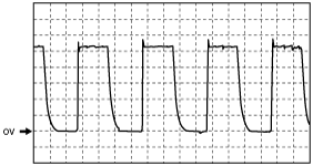
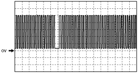
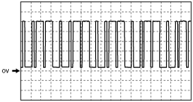
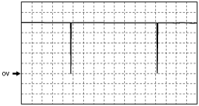
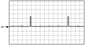
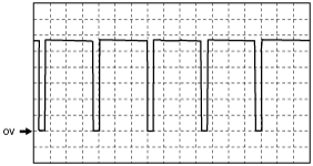
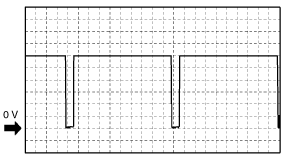
Inspection Using An Oscilloscope (Reference)
am6zzw00007996
|
am6zzw00007997
|
am6zzw00007998
|
am6zzw00007999
|
am6zzw00008000
|
am6zzw00008001
|
am6zzw00008002
|
am6zzw00008003
|
am6zzw00008004
|
am6zzw00008005
|