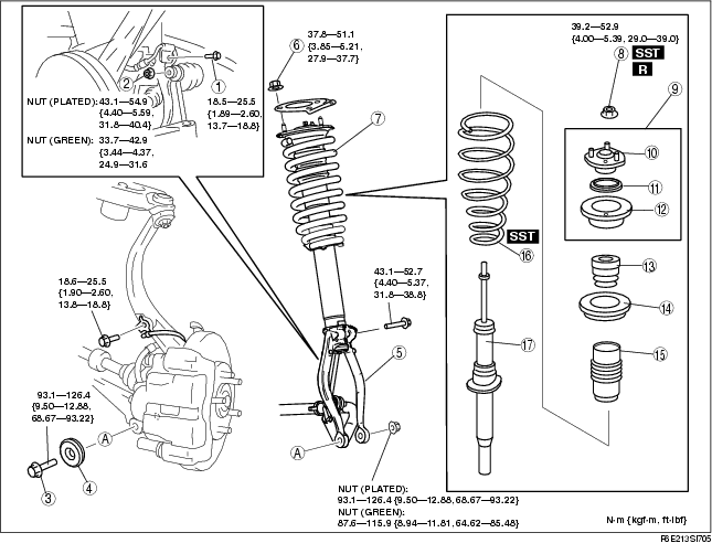
1. Remove in the order indicated in the table.
2. Install in the reverse order of removal.
.
|
1
|
Bolt (brake hose bracket)
|
|
2
|
Nut (front stabilizer control link)
|
|
3
|
Bolt (front shock absorber lower side)
|
|
4
|
Dynamic damper
|
|
5
|
Damper fork
|
|
6
|
Nut (front shock absorber upper side)
|
|
7
|
Front shock absorber and coil spring
|
|
8
|
Piston rod nut
(See Piston Rod Nut Removal Note.)
|
|
9
|
Mounting rubber assy
|
|
10
|
Mounting rubber
|
|
11
|
Bearing
|
|
12
|
Spring seat
|
|
13
|
Bound stopper
|
|
14
|
Spring seat rubber
|
|
15
|
Dust boot
|
|
16
|
Coil spring
|
|
17
|
Front shock absorber
|
1. Support the knuckle with a jack to prevent from falling.
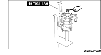
1. Protect the coil spring using a piece of cloth, then set the SSTs.
2. Compress the coil spring using the SSTs, and remove the piston rod nut.
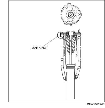
1. Temporarily install the coil spring, dust boot and mounting rubber on the shock absorber so that the lower end of the coil spring is seated on the step of the lower spring seat.
2. Mark the coil spring, dust boot and mounting rubber for proper installation as shown in the figure.
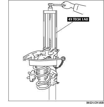
3. Align the marks of the coil spring and dust boot. Protect the coil spring and dust boot using a piece of cloth, then set the SSTs.
4. Compress the coil spring using the SSTs.
5. Install the shock absorber so that the lower end of the coil spring is seated on the step of the lower spring seat.
6. Make sure that the marks on the shock absorber and dust boot are aligned.
7. Install the mounting rubber and piston rod nut, then remove the SSTs.
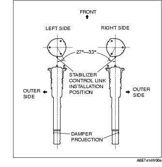
Piston rod nut tightening torque1. Install the stud bolts at a 27°-33° angle from where the stabilizer control link is installed (center line), towards the inner side of the vehicle.
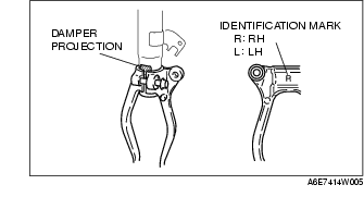
1. Align the gap of the damper fork with the projections of the damper
2. Tighten the bolt.