|
STEP
|
INSPECTION
|
ACTION
|
|
1
|
VERIFY FREEZE FRAME DATA HAS BEEN RECORDED
• Has FREEZE FRAME PID DATA been recorded?
|
Yes
|
Go to next step.
|
|
No
|
Record FREEZE FRAME PID DATA on repair order, then go to next step.
|
|
2
|
VERIFY RELATED REPAIR INFORMATION AVAILABILITY
• Check for related Service Bulletins and/or on-line repair information availability.
• Is any related repair information available?
|
Yes
|
Perform repair or diagnosis according to available repair information.
• If vehicle is not repaired, go to next step.
|
|
No
|
Go to next step.
|
|
3
|
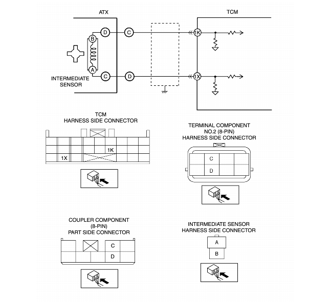
INSPECT TERMINAL COMPONENT NO.2 (8-PIN) CONNECTOR FOR POOR CONNECTION
• Turn ignition key to OFF.
• Disconnect terminal component No.2 (8-pin) connector.
• Check for poor connection (damaged, pulled-out terminals, corrosion, etc.).
• Are terminals okay?
|
Yes
|
Go to next step.
|
|
No
|
Repair or replace terminals, then go to Step 12.
|
|
4
|
INSPECT INTERMEDIATE SENSOR RESISTANCE
• Measure resistance between terminal component No.2 (8-pin) (transaxle case side).
• Is resistance within 513-627 ohms between terminal component No.2 (8-pin) terminal C and D (transaxle case side)?
|
Yes
|
Go to next step.
|
|
No
|
Go to Step 8
|
|
5
|
INSPECT TCM CONNECTOR FOR POOR CONNECTION
• Disconnect TCM connector.
• Check for poor connection (damaged, pulled-out terminals, corrosion, etc.).
• Are terminals okay?
|
Yes
|
Go to next step.
|
|
No
|
Repair terminals, then go to Step 12.
|
|
6
|
INSPECT TERMINAL COMPONENT NO.2 (8-PIN) CIRCUIT FOR OPEN
• Check terminal component No.2 (8-pin) terminals (harness-side) and TCM terminals (harness-side).
-
- C and 1K
-
- D and 1X
• Is there continuity?
|
Yes
|
Go to next step.
|
|
No
|
Repair or replace harness, then go to Step 12.
|
|
7
|
INSPECT TERMINAL COMPONENT NO.2 (8-PIN) CIRCUIT FOR SHORT TO GROUND
• Check terminal component No.2 (8-pin) terminal (harness-side) and body ground.
-
- C and body ground
-
- D and body ground
• Is there any continuity?
|
Yes
|
Repair or replace harness, then go to Step 12.
|
|
No
|
Go to Step 12.
|
|
8
|
INSPECT COUPLER COMPONENT (8-PIN) CONNECTOR FOR POOR CONNECTION
• Disassemble the control valve body cover.
• Disconnect coupler component (8-pin) connector.
• Check for poor connection (damaged, pulled-out terminals, corrosion, etc.).
• Are terminals okay?
|
Yes
|
Go to next step.
|
|
No
|
Repair terminals, then go to Step 12.
|
|
9
|
INSPECT INTERMEDIATE SENSOR RESISTANCE
• Measure resistance between coupler component (8-pin).
• Is resistance within 513-627 ohms between coupler component (8-pin) terminal D and C (part side)?
|
Yes
|
Repair or replace coupler component, then go to Step 12.
|
|
No
|
Go to next step.
|
|
10
|
INSPECT INTERMEDIATE SENSOR CONNECTOR FOR POOR CONNECTION
• Disassemble the transaxle.
• Disconnect intermediate sensor connector.
• Check for poor connection (damaged, pulled-out terminals, corrosion, etc.).
• Are terminals okay?
|
Yes
|
Go to next step.
|
|
No
|
Repair terminals, then go to Step 12.
|
|
11
|
INSPECT INTERMEDIATE SENSOR RESISTANCE
• Measure resistance between intermediate sensor.
• Is resistance within 513-627 ohms between intermediate sensor connector terminal A and B (part side)?
|
Yes
|
Repair or replace coupler component, then go to next step.
|
|
No
|
Replace intermediate sensor, then go to next step.
|
|
12
|
VERIFY TROUBLESHOOTING OF DTC P0715 COMPLETED
• Make sure to reconnect all disconnected connectors.
• Clear DTC from memory using WDS or equivalent.
• Drive vehicle with vehicle speed 40 km/h {25 mph} or above and engine speed 1500 rpm or above for 2 second or more
• Repeat Step ii two times.
• Is same DTC present?
|
Yes
|
Replace TCM, then go to next step.
|
|
No
|
Go to next step.
|
|
13
|
VERIFY AFTER REPAIR PROCEDURE
• Perform "After Repair Procedure".
• Is there any DTC present?
|
Yes
|
Go to applicable DTC inspection.
|
|
No
|
Troubleshooting completed.
|