|
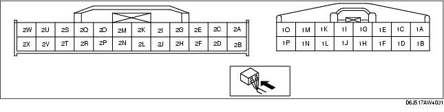
Terminal
|
Signal
|
Connected to
|
Test condition
|
Voltage (V)
|
Action
|
|
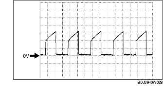
1A
|
Shift solenoid A control
|
Shift solenoid A
|
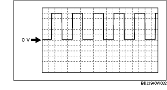
• Inspect using the wave profile.
|
• Inspect shift solenoid A
• Inspect related harness
|
|
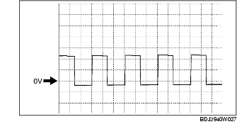
1B
|
Shift solenoid B control
|
Shift solenoid B
|
• Inspect using the wave profile.
|
• Inspect shift solenoid B
• Inspect related harness
|
|
1C
|
Shift solenoid C control
|
Shift solenoid C
|
• Inspect using the wave profile.
|
• Inspect shift solenoid C
• Inspect related harness
|
|
1D
|
Pressure control solenoid B
|
Pressure control solenoid B
|
• Inspect using the wave profile.
|
• Inspect pressure control solenoid B
• Inspect related harness
|
|
1E
|
Pressure control solenoid A (+)
|
Pressure control solenoid A
|
• Inspect using the wave profile.
|
• Inspect pressure control solenoid A
• Inspect related harness
|
|
1F
|
Shift solenoid D control
|
Shift solenoid D
|
Selector lever is at P, N, D (2GR, 4GR, 5GR), M (1GR) position
|
B+
|
• Inspect shift solenoid D
• Inspect related harness
|
|
Other
|
Below 1.0
|
|
1G
|
Pressure control solenoid A (-)
|
Pressure control solenoid A
|
• Inspect using the wave profile.
|
• Inspect pressure control solenoid A
• Inspect related harness
|
|
1H
|
Shift solenoid E control
|
Shift solenoid E
|
Detects TCC operation
|
B+
|
• Inspect shift solenoid E
• Inspect related harness
|
|
Other
|
Below 1.0
|
|
1I
|
-
|
-
|
-
|
-
|
-
|
|
1J
|
Shift solenoid F control
|
Shift solenoid F
|
1GR, 2GR, 3GR, 4GR
|
B+
|
• Inspect shift solenoid F
• Inspect related harness
|
|
5GR
|
Below 1.0
|
|
1K
|
Back-up power supply
|
Battery (positive terminal)
|
Under any condition
|
B+
|
• Inspect battery
• Inspect related harness
|
|
1L
|
Vehicle speed output
|
BCM
|
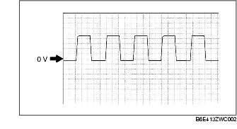
• Inspect using the wave profile.
|
• Inspect VSS
• Inspect BCM
• Inspect related harness
|
|
1M
|
B+
|
Main relay
|
Ignition switch OFF
|
Below 1.0
|
• Inspect battery
• Inspect related harness
|
|
Ignition switch ON
|
B+
|
|
1N
|
B+
|
Main relay
|
Ignition switch OFF
|
Below 1.0
|
• Inspect battery
• Inspect related harness
|
|
Ignition switch ON
|
B+
|
|
1O
|
GND
|
GND
|
Under any condition
|
Below 1.0
|
• Inspect related harness
|
|
1P
|
GND
|
GND
|
Under any condition
|
Below 1.0
|
• Inspect related harness
|
|
2A
|
-
|
-
|
-
|
-
|
-
|
|
2B
|
M range
|
M range switch
|
Ignition switch ON
|
Manual mode
|
Below 1.0
|
• Inspect M range switch
• Inspect related harness
|
|
Other
|
B+
|
|
2C
|
-
|
-
|
-
|
-
|
-
|
|
2D
|
Manual up
|
Up switch
|
Ignition switch ON
|
Detects up-shift operation of selector lever in M range
|
Below 1.0
|
• Inspect up switch
• Inspect related harness
|
|
Other
|
B+
|
|
2E
|
-
|
-
|
-
|
-
|
-
|
|
2F
|
Manual down
|
Down switch
|
Ignition switch ON
|
Detects down-shift operation of selector lever in M range
|
Below 1.0
|
• Inspect down switch
• Inspect related harness
|
|
Other
|
B+
|
|
2G
|
-
|
-
|
-
|
-
|
-
|
|
2H
|
Selector lever position
|
TR switch
(terminal C)
|
Ignition switch ON
|
P position
|
Approx. 4.6
|
• Inspect TR switch
• Inspect related harness
|
|
R position
|
Approx. 3.9
|
|
N position
|
Approx. 3.2
|
|
D range
M range
|
Approx. 2.5
|
|
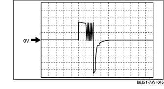
2I
|
Input/turbine speed sensor (+)
|
Input/turbine speed sensor
|
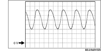
• Inspect using the wave profile.
|
• Inspect input/turbine speed sensor
• Inspect related harness
|
|
2J
|
Oil pressure
|
Oil pressure switch
|
Ignition switch ON
|
Detects forward clutch pressure
|
Below 1.0
|
• Inspect oil pressure switch
• Inspect related harness
|
|
Other
|
B+
|
|
2K
|
Input/turbine speed sensor (-)
|
Input/turbine speed sensor
|
• Inspect using the wave profile.
|
• Inspect input/turbine speed sensor
• Inspect related harness
|
|
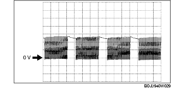
2L
|
Secondary gear rotating speed
|
Intermediate sensor
|
• Inspect using the wave profile.
|
• Inspect intermediate sensor
• Inspect related harness
|
|
2M
|
ATF temperature
|
TFT sensor
|
Ignition switch ON
|
TFT 20 °C
{68 °F}
|
Approx. 3.3
|
• Inspect TFT sensor
• Inspect related harness
|
|
TFT 40 °C
{104 °F}
|
Approx. 2.4
|
|
TFT 60 °C
{140 °F}
|
Approx. 1.5
|
|
2N
|
-
|
-
|
-
|
-
|
-
|
|
2O
|
Sensor GND
|
MAF/IAT sensor, A/F sensor, HO2S, Variable resistor, ECT sensor, TP sensor, MAP sensor, TFT sensor, TR switch
|
Under any condition
|
Below 1.0
|
• Inspect related harness
|
|
2P
|
Vehicle speed
|
VSS
|
• Inspect using the wave profile.
|
• Inspect VSS
• Inspect related harness
|
|
2Q
|
-
|
-
|
-
|
-
|
-
|
|
2R
|
Main relay control
|
Main relay
|
Ignition switch OFF
|
B+
|
• Inspect main relay
• Inspect related harness
|
|
Ignition switch ON
|
Below 1.0
|
|
2S
|
-
|
-
|
-
|
-
|
-
|
|
2T
|
-
|
-
|
-
|
-
|
-
|
|
2U
|
-
|
-
|
-
|
-
|
-
|
|
2V
|
-
|
-
|
-
|
-
|
-
|
|
2W
|
CAN_H
|
Instrument cluster, ABS HU/CM, ABS/TCS HU/CM, DSC HU/CM
|
Because this terminal is for CAN, adequate determination by terminal voltage is not possible.
|
-
|
|
2X
|
CAN_L
|
Instrument cluster, ABS HU/CM, ABS/TCS HU/CM, DSC HU/CM
|
Because this terminal is for CAN, adequate determination by terminal voltage is not possible.
|
-
|