1. Remove the battery.
2. Discharge the refrigerant from the system. (See REFRIGERANT RECOVERY.) (See REFRIGERANT CHARGING.)
3. Remove the front bumper. (L.H.D.) (See FRONT BUMPER REMOVAL/INSTALLATION.)
4. Remove the front combination light (LH). (L.H.D.) (See FRONT COMBINATION LIGHT REMOVAL/INSTALLATION.)
5. Remove the air cleaner cover, air cleaner element and air cleaner case. (See INTAKE AIR SYSTEM REMOVAL/INSTALLATION [L8, LF, L3].)
6. Remove the splash shield.
7. Remove the shroud panel. (See SHROUD PANEL REMOVAL/INSTALLATION.)
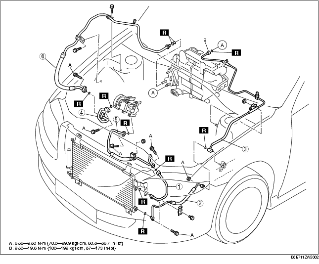
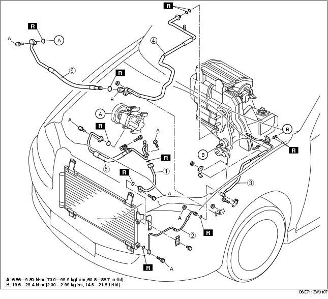
9. Remove in the order indicated in the table. Do not allow compressor oil to spill.
10. Install in the reverse order of removal.
11. Perform the refrigerant system performance test. (See REFRIGERANT SYSTEM PERFORMANCE TEST.)
L.H.D. (L8, LF, L3)
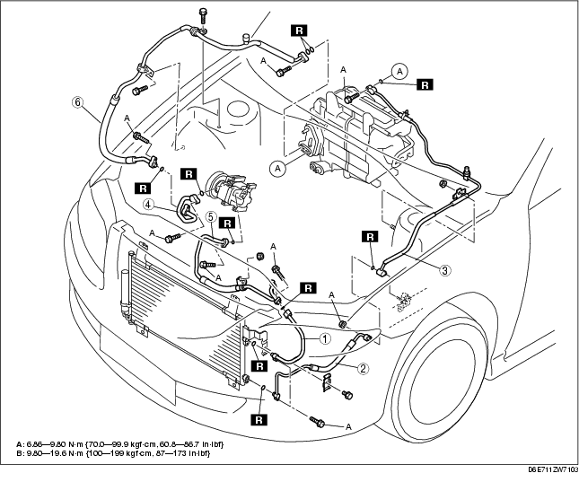
L.H.D. (L3 Turbo)
R.H.D.
.
|
1
|
Cooler pipe No.1
|
|
2
|
Cooler pipe No.2
|
|
3
|
Cooler pipe No.3
|
|
4
|
Cooler pipe No.4
|
|
5
|
Cooler hose (HI)
|
|
6
|
Cooler hose (LO)
|
1. Loosen the nut using two spanners, then remove the cooler pipe or hose.
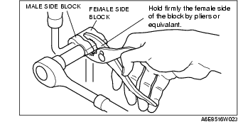
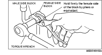
1. Disconnect the block joint type pipes by grasping female side of the block with pliers or similar tool and holding firmly, then remove the connection bolt or nut.
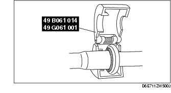
1. Set the SST.
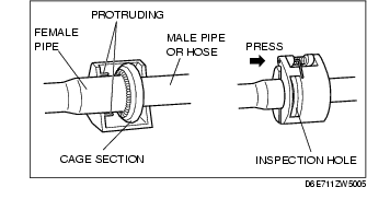
2. While looking through the inspection hole of the SST, insert the protruding part of the SST until it makes contact with the cage section.
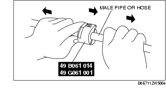
3. Use the SST to disconnect the male pipe or hose from the female by pulling the male pipe or hose.
1. When installing a new cooler pipe No.4 or cooler hose (LO), add a supplemental amount of ATMOS GU10 compressor oil into the refrigeration cycle.
Supplemental amount (approx. quantity)2. Apply compressor oil to the O-rings and connect the joints.
3. Tighten the joints.
1. Tighten the nut or bolt of joint by hand.
2. Tighten the joint to the specified torque. If it is a nut joint, tighten the nut with a spanner and torque wrench.
3. Connect the block joint type pipes by grasping the female side of the block with pliers or similar tool and holding firmly, then tighten the connection bolt or nut with a torque wrench.
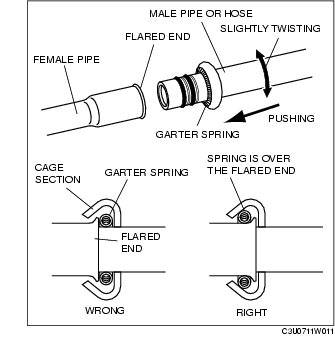
1. Connect the male pipe or hose by twisting it onto female pipe until the garter spring at the male pipe or hose is over the flared end of female pipe.