|
STEP
|
INSPECTION
|
ACTION
|
|
1
|
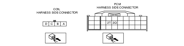
INSPECT POWER SUPPLY CIRCUIT OF COIL ANTENNA
• Disconnect coil antenna connector.
• Turn ignition switch to ON position.
• Measure voltage at terminal D of coil antenna connector.
• Is voltage more than 8 V?
|
Yes
|
Go to next step.
|
|
No
|
Repair wiring harness.
|
|
2
|
INSPECT WIRING HARNESS BETWEEN COIL ANTENNA AND GROUND
• Turn ignition switch to LOCK position.
• Inspect wiring harness between coil antenna connector terminal C and ground for following.
-
- Short to power supply
-
- Open circuit
• Is wiring harness okay?
|
Yes
|
Go to next step.
|
|
No
|
Repair wiring harness.
|
|
3
|
INSPECT COIL ANTENNA INPUT SIGNAL CIRCUIT
• Connect coil antenna connector.
• Turn ignition switch to ON position.
• Measure voltage at terminal B of coil antenna connector.
• Is voltage more than 8 V?
|
Yes
|
Go to Step 7.
|
|
No
|
Go to next step.
|
|
4
|
INSPECT COIL ANTENNA INPUT SIGNAL CIRCUIT
• Turn ignition switch to LOCK position.
• Disconnect PCM connector.
• Turn ignition switch to ON position.
• Measure voltage at terminal 2T of PCM connector.
• Is voltage more than 8 V?
|
Yes
|
Replace PCM and reprogram immobilizer system.
|
|
No
|
Go to next step.
|
|
5
|
INSPECT COMMUNICATION CIRCUIT (INPUT) FOR CONTINUITY
• Turn ignition switch to LOCK position.
• Disconnect coil antenna and PCM connectors.
• Is there continuity between coil antenna connector terminal B and PCM connector terminal 2T?
|
Yes
|
Go to next step.
|
|
No
|
Repair wiring harness.
|
|
6
|
INSPECT COIL ANTENNA INPUT SIGNAL CIRCUIT
• Measure resistance between coil antenna connector terminal B and ground.
• Is resistance more than 10 kilohms?
|
Yes
|
Replace coil antenna.
|
|
No
|
Repair wiring harness.
|
|
7
|
INSPECT COIL ANTENNA OUTPUT SIGNAL CIRCUIT
• Connect coil antenna and PCM connectors.
• Turn ignition switch to ON position.
• Measure voltage at terminal A of coil antenna connector.
• Is voltage more than 8 V?
|
Yes
|
Replace coil antenna.
|
|
No
|
Go to next step.
|
|
8
|
INSPECT COIL ANTENNA OUTPUT SIGNAL CIRCUIT
• Turn ignition switch to LOCK position.
• Disconnect coil antenna connector.
• Turn ignition switch to ON position.
• Measure voltage at terminal A of coil antenna connector.
• Is voltage more than 8 V?
|
Yes
|
Replace coil antenna.
|
|
No
|
Go to next step.
|
|
9
|
INSPECT COMMUNICATION CIRCUIT (OUTPUT) FOR CONTINUITY
• Turn ignition switch to LOCK position.
• Disconnect PCM connector.
• Is there continuity between coil antenna connector terminal A and PCM connector terminal 2Q?
|
Yes
|
Go to next step.
|
|
No
|
Repair wiring harness.
|
|
10
|
INSPECT COIL ANTENNA OUTPUT SIGNAL CIRCUIT
• Measure resistance between PCM connector terminal 2Q and ground.
• Is resistance more than 10 kilohms?
|
Yes
|
Replace PCM and reprogram immobilizer system.
|
|
No
|
Repair wiring harness.
|