|
1
|
RECORD VEHICLE STATUS WHEN DTC WAS DETECTED TO UTILIZE WITH REPEATABILITY VERIFICATION
• Record the freeze frame data/snapshot data.
-
Note
-
• Recording can be facilitated using the screen capture function of the PC.
|
—
|
Go to the next step.
|
|
2
|
VERIFY RELATED REPAIR INFORMATION OR SERVICE INFORMATION AVAILABILITY
• Verify related Service Bulletins, on-line repair information, or Service Information availability.
• Is any related Information available?
|
Yes
|
Perform repair or diagnosis according to the available information.
• If the vehicle is not repaired, go to the next step.
|
|
No
|
Go to the next step.
|
|
3
|
INSPECT FOR OTHER RELATED DTCs
• Perform the DTC inspection for the PCM.
• Are any other DTCs displayed?
|
Yes
|
Repair the malfunctioning location according to the applicable DTC troubleshooting.
|
|
No
|
Go to the next step.
|
|
4
|
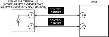
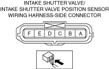
INSPECT INTAKE SHUTTER VALVE CONNECTOR FOR MALFUNCTION
• Inspect the applicable connector and terminal.
• Are the connector and terminal normal?
|
Yes
|
Go to the next step.
|
|
No
|
Repair or replace the malfunctioning location and perform the repair completion verification.
|
|
5
|
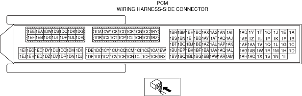
INSPECT PCM CONNECTOR FOR MALFUNCTION
• Inspect the applicable connector and terminal.
• Are the connector and terminal normal?
|
Yes
|
Go to the next step.
|
|
No
|
Repair or replace the malfunctioning location and perform the repair completion verification.
|
|
6
|
INSPECT INTAKE SHUTTER VALVE CONTROL CIRCUIT FOR OPEN CIRCUIT
• Inspect the applicable circuit for open circuit.
• Is the circuit normal?
|
Yes
|
Go to the next step.
|
|
No
|
Repair or replace the malfunctioning location and perform the repair completion verification.
|
|
7
|
INSPECT INTAKE SHUTTER VALVE FOR MALFUNCTION
• Inspect the applicable part.
• Is the part normal?
|
Yes
|
Go to the next step.
|
|
No
|
Repair or replace the malfunctioning location and perform the repair completion verification.
|
|
8
|
INSPECT INTAKE SHUTTER VALVE FOR FOREIGN MATTER
• Remove the intake shutter valve.
• Inspect the intake shutter valve for foreign matter.
• Is there foreign matter in the intake shutter valve?
|
Yes
|
Remove the foreign matter from the intake shutter valve, then go to repair completion verification.
|
|
No
|
Go to the next step.
|
|
9
|
INSPECT INTAKE SHUTTER VALVE POSITION SENSOR FOR MALFUNCTION
• Inspect the applicable part.
• Is the part normal?
|
Yes
|
Go to the next step.
|
|
No
|
Repair or replace the malfunctioning location and perform the repair completion verification.
|
|
Repair completion verification 1
|
VERIFY THAT VEHICLE IS REPAIRED
• Install/connect the part removed/disconnected during the troubleshooting procedure.
• Clear the DTC recorded in the memory.
• Replicate the vehicle conditions at the time the DTC was detected using the following procedure.
-
― Drive the vehicle on flat roads under the following conditions 5 times repeatedly.
-
1. Idle the engine for 20 s.
2. Accelerate in 2nd gear to 35 km/h {22 mph} and drive the vehicle while maintaining the speed for 25 s.
3. Stop the vehicle and idle the engine for 20 s.
4. Accelerate in 3rd gear to 50 km/h{31 mph} and drive the vehicle while maintaining the speed for 50 s.
5. Stop the vehicle and idle the engine for 20 s.
• Perform the DTC inspection for the PCM.
• Is the same Pending DTC present?
|
Yes
|
Refer to the controller area network (CAN) malfunction diagnosis flow to inspect for a CAN communication error.
If the CAN communication is normal, perform the diagnosis from Step 1.
• If the malfunction recurs, replace the PCM, then go to the next step.
|
|
No
|
Go to the next step.
|
|
Repair completion verification 2
|
VERIFY IF OTHER DTCs DISPLAYED
• Perform the DTC inspection.
• Are any other DTCs displayed?
|
Yes
|
Repair the malfunctioning location according to the applicable DTC troubleshooting.
|
|
No
|
DTC troubleshooting completed.
|