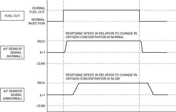
If the response speed of the A/F sensor is delayed, the PCM determines an A/F sensor malfunction and stores a DTC.
am3zzw00033698
|
DTC P0133:00 [PCM (SKYACTIV-X)]
id0102u9702400
Details On DTCs
|
Description |
A/F sensor circuit slow response |
|
|---|---|---|
|
Detection condition
|
Determination conditions
|
• The response speed of the A/F sensor input signal when the air/fuel ratio is fluctuated is slow.
|
|
Preconditions
|
• Engine speed: Within specified range
• Engine coolant temperature: Specified value or more
• Mass airflow: Within specified range
• i-stop control is not operating
• The following DTCs are not detected:
|
|
|
Drive cycle
|
• 2
|
|
|
Self test type
|
• CMDTC self test
|
|
|
Sensor used
|
• A/F sensor
|
|
|
Fail-safe function
|
• Fixes duty value of A/F sensor heater
• Stops fuel feedback control of A/F sensor
• Inhibits the EGR control.
|
|
|
Vehicle status when DTCs are output
|
• Not applicable
|
|
|
Possible cause
|
• A/F sensor signal malfunction
• A/F sensor deterioration
• A/F sensor heater malfunction
• PCM malfunction
|
|
System Wiring Diagram
Function Explanation (DTC Detection Outline)
am3zzw00033698
|
Repeatability Verification Procedure
PID Item/Simulation Item Used In Diagnosis
PID/DATA monitor item table
|
PIDs |
Reference |
|---|---|
|
A/F_SEN_HEAT
|
|
|
A/F_SEN_CUR
|
Function Inspection Using M-MDS
|
Step |
Inspection |
Results |
Action |
|---|---|---|---|
|
1
|
PURPOSE: VERIFY RELATED REPAIR INFORMATION OR SERVICE INFORMATION AVAILABILITY
• Verify related Service Bulletins, on-line repair information, or Service Information availability.
• Is any related Information available?
|
Yes
|
Perform repair or diagnosis according to the available information.
• If the vehicle is not repaired, go to the next step.
|
|
No
|
Go to the next step.
|
||
|
2
|
PURPOSE: IDENTIFY TRIGGER DTC FOR FREEZE FRAME DATA
• Is the DTC P0133:00 on freeze frame data?
|
Yes
|
Go to the next step.
|
|
No
|
Go to the troubleshooting procedure for DTC on freeze frame data.
(See DTC TABLE [PCM (SKYACTIV-X)].)
|
||
|
3
|
PURPOSE: RECORD VEHICLE STATUS WHEN DTC WAS DETECTED TO UTILIZE WITH REPEATABILITY VERIFICATION
• Record the freeze frame data/snapshot data.
|
—
|
Go to the next step.
|
|
4
|
PURPOSE: INSPECT FOR OTHER RELATED DTCs
• Perform the DTC inspection for the PCM.
(See DTC INSPECTION.)
• Are any of the following DTCs displayed?
|
Yes
|
Repair the malfunctioning location according to the applicable DTC troubleshooting.
|
|
No
|
Go to the next step.
|
||
|
5
|
PURPOSE: VERIFY A/F SENSOR
• Start the engine and idle it.
• Access the A/F_SEN_CUR PID using the M-MDS.
(See PID/DATA MONITOR INSPECTION.)
• Is the A/F_SEN_CUR PID value normal?
|
Yes
|
Go to the next step.
|
|
No
|
Go to Troubleshooting Diagnostic Procedure to perform the procedure from Step 1.
|
||
|
6
|
PURPOSE: VERIFY A/F SENSOR HEATER
• Start the engine and idle it.
• Access the A/F_SEN_HEAT PID using the M-MDS.
(See PID/DATA MONITOR INSPECTION.)
• Is the A/F_SEN_HEAT PID value normal?
|
Yes
|
Go to the next step.
|
|
No
|
Go to Troubleshooting Diagnostic Procedure to perform the procedure from Step 5.
|
||
|
7
|
PURPOSE: INSPECT FOR OTHER RELATED DTCs
• Perform the DTC inspection for the PCM.
(See DTC INSPECTION.)
• Are any other DTCs displayed?
|
Yes
|
Repair the malfunctioning location according to the applicable DTC troubleshooting.
(See DTC TABLE [PCM (SKYACTIV-X)].)
Go to Troubleshooting Diagnostic Procedure to perform the procedure from Step 1.
|
|
No
|
Go to Troubleshooting Diagnostic Procedure to perform the procedure from Step 1.
|
Troubleshooting Diagnostic Procedure
|
Step |
Inspection |
Results |
Action |
|---|---|---|---|
|
1
|
PURPOSE: INSPECT A/F SENSOR CONNECTOR FOR MALFUNCTION
• Inspect the applicable connector and terminal.
(See CONNECTOR INSPECTION.)
• Are the connector and terminal normal?
|
Yes
|
Go to the next step.
|
|
No
|
Repair or replace the malfunctioning location and perform the repair completion verification.
|
||
|
2
|
PURPOSE: VERIFY IF A/F SENSOR IS INSTALLED CORRECTLY
• Verify the A/F sensor installation condition.
• Is the installation condition normal?
|
Yes
|
Go to the next step.
|
|
No
|
Correctly install the A/F sensor and perform the repair completion verification.
|
||
|
3
|
PURPOSE: VERIFY IF MALFUNCTION RELATED TO EMISSION SYSTEM AFFECTS A/F SENSOR SIGNAL
• Inspect for exhaust gas leakage from the exhaust system. (between A/F sensor and HO2S)
• Is there any malfunction?
|
Yes
|
Repair or replace the malfunctioning location and perform the repair completion verification.
|
|
No
|
Go to the next step.
|
||
|
4
|
PURPOSE: INSPECT A/F SENSOR FOR MALFUNCTION
• Inspect the applicable part.
• Is the part normal?
|
Yes
|
Go to the next step.
|
|
No
|
Repair or replace the malfunctioning location and perform the repair completion verification.
|
||
|
5
|
PURPOSE: INSPECT A/F SENSOR HEATER FOR MALFUNCTION
• Inspect the applicable part.
• Is the part normal?
|
Yes
|
Go to the next step.
|
|
No
|
Repair or replace the malfunctioning location and perform the repair completion verification.
|
||
|
Repair completion verification
|
PURPOSE: VERIFY THAT VEHICLE IS REPAIRED
• Install/connect the part removed/disconnected during the troubleshooting procedure.
• Clear the DTC recorded in the memory.
(See CLEARING DTC.)
• Replicate the vehicle conditions at the time the DTC was detected using the following procedure.
• Perform the DTC inspection for the PCM.
(See DTC INSPECTION.)
• Is the same Pending DTC present?
|
Yes
|
Refer to the controller area network (CAN) malfunction diagnosis flow to inspect for a CAN communication error.
If the CAN communication is normal, perform the diagnosis from Step 1.
• If the malfunction recurs, replace the PCM.
|
|
No
|
DTC troubleshooting completed.
|