DTC P220E:00 [PCM (SKYACTIV-X)]
Home
Note
• To determine the malfunctioning part, proceed with the diagnostics from "Function Inspection Using M-MDS".
Description
Nox sensor heater circuit range/performance problem
Detection condition
Determination conditions
• Any one of the following conditions is met:
― After dew point end detection is completed, heater temperature does not increase even after 110 s have elapsed
― After heater temperature increases, NOx sensor is not activated even after 110 s have elapsed.
Preconditions
• The following conditions are met:
― NOx sensor power supply voltage:9.8—16 V
― The following DTCs is not detected:
• NOx sensor:P2200:00, P2205:00, P220A:00, U029D:00
Drive cycle
• 2
Self test type
• CMDTC self test
Sensor used
• NOx sensor
Fail-safe function
• Inhibits the SPCCI control with a large amount of intake air introduced (lean A/F).
Vehicle status when DTCs are output
• Not applicable
Possible cause
• NOx sensor connector or terminals malfunction
• PCM connector or terminals malfunction
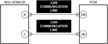
• Open or short in NOx sensor CAN communication line
• NOx sensor malfunction
• PCM malfunction
• NOx sensor performs diagnosis independently and if it detects an open or short circuit, it sends a malfunction signal to the PCM. When the malfunction signal is received from NOx sensor, the PCM stores a DTC.
1. Display the PID NOX_SEN_ACTIVITY using the M-MDS. (See PID/DATA MONITOR INSPECTION
2. Drive the vehicle until the PID NOX_SEN_ACTIVITY value turns on.
PID/DATA monitor item table
PIDs
Reference
NOX_SEN_ACTIVITY
Step
Inspection
Results
Action
1
PURPOSE: RECORD VEHICLE STATUS WHEN DTC WAS DETECTED TO UTILIZE WITH REPEATABILITY VERIFICATION
• Record the freeze frame data/snapshot data.
Note
• Recording can be facilitated using the screen capture function of the PC.
—
Go to the next step.
2
PURPOSE: VERIFY RELATED REPAIR INFORMATION OR SERVICE INFORMATION AVAILABILITY
• Verify related Service Bulletins, on-line repair information, or Service Information availability.
• Is any related Information available?
Yes
Perform repair or diagnosis according to the available information.
• If the vehicle is not repaired, go to the next step.
No
Go to the next step.
3
PURPOSE: INSPECT FOR OTHER RELATED DTCs
• Perform the DTC inspection for the PCM.
• Are any DTCs displayed?
Yes
Repair the malfunctioning location according to the applicable DTC troubleshooting.
Go to Troubleshooting Diagnostic Procedure to perform the repair completion verification.
No
Go to Troubleshooting Diagnostic Procedure to perform the procedure from Step 1.
Intention of troubleshooting procedure
• Step1—3
― Perform an inspection of the connectors and wiring harnesses between the PCM and NOx sensor.
• Step4
― Perform a unit inspection of the NOx sensor.
• Repair completion verification
― Verify that the primary malfunction is resolved and there are no other malfunctions.
Step
Inspection
Results
Action
1
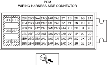
PURPOSE: INSPECT PCM CONNECTOR FOR MALFUNCTION
• Inspect the applicable connector and terminal.
• Are the connector and terminal normal?
Yes
Go to the next step.
No
Repair or replace the malfunctioning location and perform the repair completion verification.
2
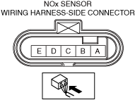
PURPOSE: INSPECT NOx SENSOR CONNECTOR FOR MALFUNCTION
• Inspect the applicable connector and terminal.
• Are the connector and terminal normal?
Yes
Go to the next step.
No
Repair or replace the malfunctioning location and perform the repair completion verification.
3
PURPOSE: INSPECT NOx SENSOR CAN COMMUNICATION LINE FOR SHORT OR OPEN CIRCUITT
• Inspect the applicable circuit for short or open circuit.
• Is the circuit normal?
Yes
Go to the next step.
No
Repair or replace the malfunctioning location and perform the repair completion verification.
4
PURPOSE: INSPECT NOx SENSOR FOR MALFUNCTION
• Inspect the applicable part.
• Is the part normal?
Yes
Go to the next step.
No
Repair or replace the malfunctioning location and perform the repair completion verification.
Repair completion verification 1
PURPOSE: VERIFY THAT VEHICLE IS REPAIRED
• Install/connect the part removed/disconnected during the troubleshooting procedure.
• Clear the DTC recorded in the memory.
• Replicate the vehicle conditions at the time the DTC was detected using the following procedure.
― Implement the repeatability verification procedure.
• Perform the DTC inspection for the PCM.
• Is the same Pending DTC present?
Yes
Refer to the controller area network (CAN) malfunction diagnosis flow to inspect for a CAN communication error.
If the CAN communication is normal, perform the diagnosis from Step 1.
• If the malfunction recurs, replace the PCM, then go to the next step.
No
Go to the next step.
Repair completion verification 2
PURPOSE: VERIFY IF OTHER DTCs DISPLAYED
• Perform the DTC inspection.
• Are any other DTCs displayed?
Yes
Repair the malfunctioning location according to the applicable DTC troubleshooting.
No
DTC troubleshooting completed.