 |
am3zzw00027622
ENGINE MOUNT DISASSEMBLY/ASSEMBLY [SKYACTIV-G (WITHOUT CYLINDER DEACTIVATION (E))]
id0110u1806900
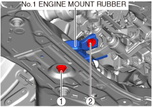
No.1 Engine Mount (2WD)
1. Remove the front under cover No.2. (See FRONT UNDER COVER No.2 REMOVAL/INSTALLATION.)
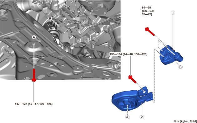
2. Remove in the order indicated in the table.
3. Install in the reverse order of removal.
am3zzw00027622
|
|
1
|
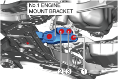
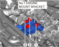
No.1 engine mount bracket
|
|
2
|
No.1 engine mount rubber
|
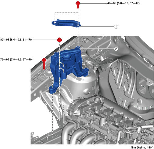
No.1 engine mount installation note (2WD)
1. Tighten the No.1 engine mount bracket installation bolts in the order shown in the figure.
am3zzw00027623
|
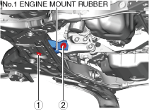
2. Temporarily tighten the No.1 engine mount rubber installation bolts in the order shown in the figure.
am3zzw00027624
|
3. Tighten the No.1 engine mount rubber installation bolts in the order shown in the figure.
am3zzw00027624
|
No.1 Engine Mount (AWD)
1. Remove the front under cover No.2. (See FRONT UNDER COVER No.2 REMOVAL/INSTALLATION.)
2. Remove in the order indicated in the table.
3. Install in the reverse order of removal.
ac30zw00003896
|
|
1
|
No.1 engine mount bracket
(See No.1 Engine Mount (AWD).)
|
|
2
|
No.1 engine mount rubber
(See No.1 Engine Mount (AWD).)
|
No.1 engine mount installation note (AWD)
1. Tighten the No.1 engine mount bracket installation bolts in the order shown in the figure.
am3zzw00031592
|
2. Temporarily tighten the No.1 engine mount rubber installation bolts in the order shown in the figure.
am3zzw00031593
|
3. Tighten the No.1 engine mount rubber installation bolts in the order shown in the figure.
am3zzw00031593
|
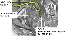
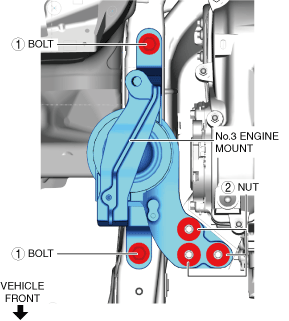
No.3 Engine Mount
1. Disconnect the negative battery terminal. (See NEGATIVE BATTERY TERMINAL DISCONNECTION/CONNECTION [(E)].)
2. Remove the plug hole plate. (See PLUG HOLE PLATE REMOVAL/INSTALLATION [SKYACTIV-G (WITHOUT CYLINDER DEACTIVATION (E))].)
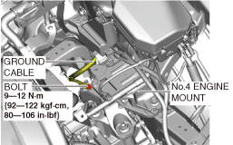
3. Remove the bolt shown in the figure and set the ground cable aside.
am3zzw00027625
|
4. Set the cooler hose (LO) aside.
5. Set the coolant reserve tank aside.
6. Remove the front under cover No.2. (See FRONT UNDER COVER No.2 REMOVAL/INSTALLATION.)
7. Remove in the order indicated in the table.
8. Install in the reverse order of removal.
am3zzw00027626
|
|
1
|
No.3 engine mount bracket
|
|
2
|
No.3 engine mount
(See No.3 Engine Mount.)
|
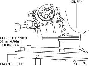
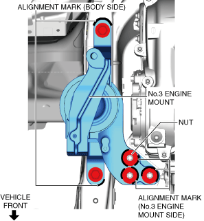
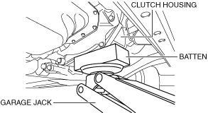
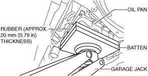
No.3 engine mount removal note
1. Before removing the No.3 engine mount, support the engine (oil pan) using a commercially available engine lifter or garage jack.
ac5uuw00006935
|
2. Place alignment marks on the locations shown in the figure so that they can be assembled to the same positions as before removal.
am3zzw00027627
|
3. Remove the No.3 engine mount.
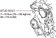
No.3 engine mount installation note
1. Tighten the engine front cover stud bolts.
am3zzw00032427
|
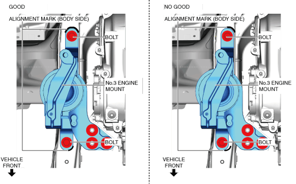
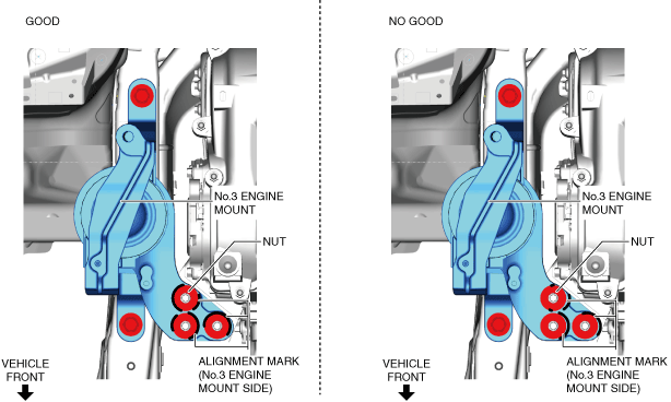
2. Temporarily tighten the No.3 engine mount installation bolts and nuts using the following procedure:
am3zzw00027628
|
am3zzw00027629
|
3. Tighten the No.3 engine mount installation bolts and nuts in the order shown in the figure.
am3zzw00027630
|
4. Remove the engine lifter or garage jack.
5. Install in the reverse order of removal.
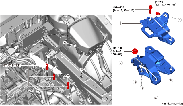
No.4 Engine Mount
1. Disconnect the negative battery terminal. (See NEGATIVE BATTERY TERMINAL DISCONNECTION/CONNECTION [(E)].)
2. Remove the air cleaner, air hose and fresh air duct as a single unit. (See INTAKE-AIR SYSTEM REMOVAL/INSTALLATION [SKYACTIV-G (WITHOUT CYLINDER DEACTIVATION (E))].)
3. Remove the PCM component. (See PCM REMOVAL/INSTALLATION [SKYACTIV-G (WITHOUT CYLINDER DEACTIVATION (E))].)
4. Remove the battery and battery tray. (See BATTERY REMOVAL/INSTALLATION [SKYACTIV-G (WITHOUT CYLINDER DEACTIVATION (E))].)
5. Remove the bolt shown in the figure and set the ground cable aside.
am3zzw00032428
|
6. Set the control cable aside. (MTX) (See CONTROL CABLE REMOVAL/INSTALLATION [C66M-R, C66MX-R].)
7. Remove the front under cover No.2. (See FRONT UNDER COVER No.2 REMOVAL/INSTALLATION.)
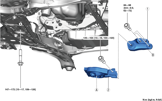
8. Remove in the order indicated in the table.
9. Install in the reverse order of removal.
Except Chinese specs.
am3zzw00034644
|
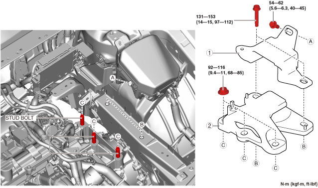
Chinese specs.
ac30zw00004304
|
|
1
|
No.4 engine mount bracket
|
|
2
|
No.4 engine mount rubber
|
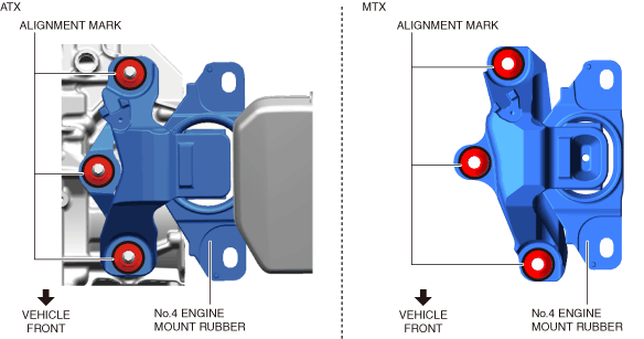
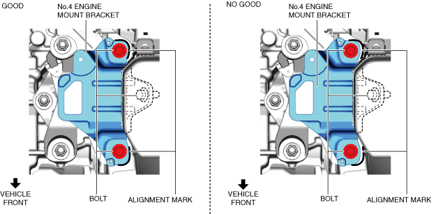
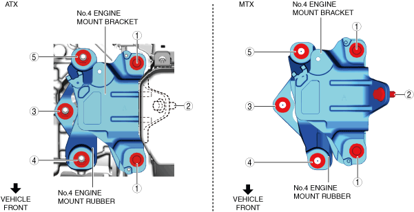
No.4 engine mount bracket removal note
am3zzw00027633
|
am3zzw00027634
|
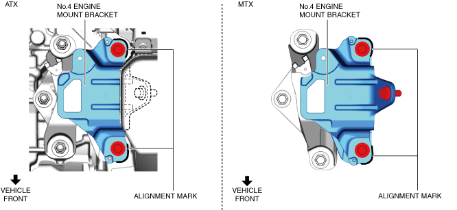
1. Place alignment marks on the locations shown in the figure so that they can be assembled to the same positions as before removal.
Except Chinese specs.
am3zzw00027635
|
Chinese specs.
ac30zw00004305
|
2. Before removing the No.4 engine mount bracket, support the transaxle using a commercially available engine lifter or garage jack.
3. Remove the No.4 engine mount bracket.
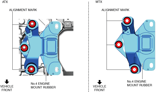
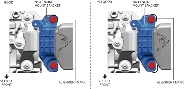
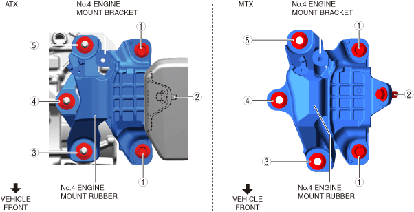
No.4 engine mount rubber removal note
1. Before removing the No.4 engine mount rubber, support the transaxle using a commercially available engine lifter or garage jack.
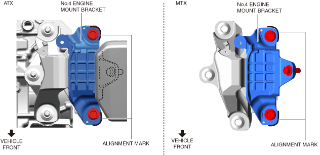
2. Place alignment marks on the locations shown in the figure so that they can be assembled to the same positions as before removal.
Except Chinese specs.
am3zzw00027636
|
Chinese specs.
ac30zw00004306
|
3. Remove the No.4 engine mount rubber.
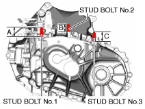
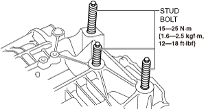
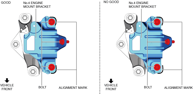
No.4 engine mount bracket and rubber installation note
1. Measure the projection of the transaxle stud bolts. (MTX)
am6xuw00011730
|
2. Tighten the transaxle stud bolts. (ATX)
am3zzw00032429
|
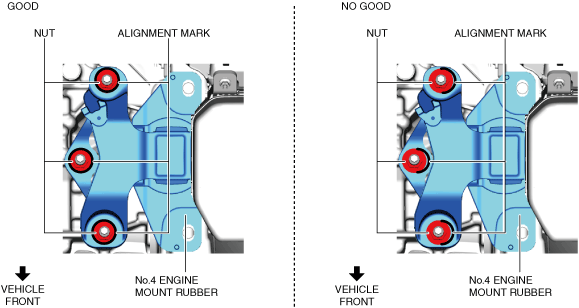
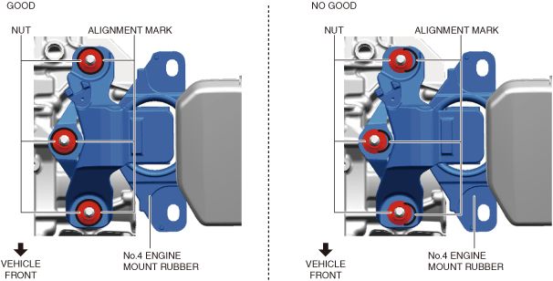
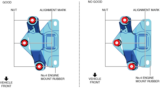
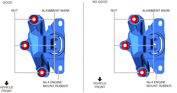
3. Align the alignment marks on the No.4 engine mount rubber and nuts, and temporarily tighten the nuts shown in the figure.
ATX (Except Chinese specs.)
am3zzw00027637
|
ATX (Chinese specs.)
ac30zw00004307
|
MTX (Except Chinese specs.)
am3zzw00027638
|
MTX (Chinese specs.)
ac30zw00004308
|
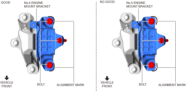
4. Align the alignment marks on the No.4 engine mount bracket and bolts, and temporarily tighten the bolts shown in the figure.
ATX (Except Chinese specs.)
am3zzw00027639
|
ATX (Chinese specs.)
ac30zw00004309
|
MTX (Except Chinese specs.)
am3zzw00027640
|
MTX (Chinese specs.)
ac30zw00004310
|
5. Install the No.4 engine mount bracket and rubber and temporarily tighten the nuts and bolts shown in the figure.
Except Chinese specs.
ac30zw00004853
|
Chinese specs.
ac30zw00004311
|