|
1
|
INSPECT BODY CONTROL MODULE (BCM) FOR MALFUNCTION
• Perform the DTC inspection for the body control module (BCM).
• Are any DTCs displayed?
|
Yes
|
Repair the malfunctioning location according to the applicable DTC troubleshooting.
|
|
No
|
Go to the next step.
|
|
2
|
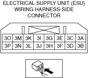
INSPECT ELECTRICAL SUPPLY UNIT (ESU) CONNECTOR FOR MALFUNCTION
• Inspect the applicable connector and terminal.
• Are the connector and terminal normal?
|
Yes
|
Go to the next step.
|
|
No
|
Repair or replace the malfunctioning location and perform the repair completion verification.
|
|
3
|
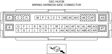
INSPECT DSC HU/CM CONNECTOR FOR MALFUNCTION
• Inspect the applicable connector and terminal.
• Are the connector and terminal normal?
|
Yes
|
Go to the next step.
|
|
No
|
Repair or replace the malfunctioning location and perform the repair completion verification.
|
|
4
|
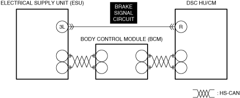
INSPECT ELECTRICAL SUPPLY UNIT (ESU) BRAKE SIGNAL CIRCUIT FOR SHORT TO GROUND
• Inspect the applicable circuit for a short to ground.
• Is the circuit normal?
|
Yes
|
Go to the next step.
|
|
No
|
Repair or replace the malfunctioning location and perform the repair completion verification.
|
|
5
|
INSPECT ELECTRICAL SUPPLY UNIT (ESU) BRAKE SIGNAL CIRCUIT FOR SHORT TO POWER SUPPLY
• Inspect the applicable circuit for a short to power supply.
• Is the circuit normal?
|
Yes
|
Go to the next step.
|
|
No
|
Repair or replace the malfunctioning location and perform the repair completion verification.
|
|
6
|
INSPECT ELECTRICAL SUPPLY UNIT (ESU) BRAKE SIGNAL CIRCUIT FOR OPEN CIRCUIT
• Inspect the applicable circuit for open circuit.
• Is the circuit normal?
|
Yes
|
Go to the next step.
|
|
No
|
Repair or replace the malfunctioning location and perform the repair completion verification.
|
|
7
|
INSPECT ELECTRICAL SUPPLY UNIT (ESU) FOR MALFUNCTION
• Install/connect the part removed/disconnected during the troubleshooting procedure.
• Measure the voltage at electrical supply unit (ESU) terminal 3L (vehicle wiring harness side) according to the brake pedal operation and verify if it changes as follows.
-
― Brake pedal released: 1.0 V or less
― Brake pedal depressed: B+
• Does the voltage change according to the brake pedal operation?
|
Yes
|
Go to the next step.
|
|
No
|
Repair or replace the malfunctioning location and perform the repair completion verification.
|
|
Repair completion verification 1
|
VERIFY THAT VEHICLE IS REPAIRED
• Install/connect the part removed/disconnected during the troubleshooting procedure.
• Clear the DTC recorded in the memory.
• Perform the work of depressing the brake pedal for 3 s or more and then releasing it for 5 times or more with the ignition switched ON (engine off or on).
• Perform the DTC inspection for the DSC HU/CM.
• Is the same Pending DTC present?
|
Yes
|
Refer to the controller area network (CAN) malfunction diagnosis flow to inspect for a CAN communication error.
If the CAN communication is normal, perform the diagnosis from Step 1.
• If the malfunction recurs, replace the DSC HU/CM, then go to the next step.
|
|
No
|
Go to the next step.
|
|
Repair completion verification 2
|
VERIFY IF OTHER DTCs DISPLAYED
• Perform the DTC inspection.
• Are any DTCs displayed?
|
Yes
|
Repair the malfunctioning location according to the applicable DTC troubleshooting.
|
|
No
|
DTC troubleshooting completed.
|