|
am3zzw00025051
BRAKE PEDAL REMOVAL/INSTALLATION [L.H.D. (E)]
id041100801256
Replacement Part
|
Brake switch
Quantity: 1
Location of use: Brake pedal
|
1. Disconnect the negative battery terminal. (See NEGATIVE BATTERY TERMINAL DISCONNECTION/CONNECTION [(E)].)
2. Remove the driver-side front heat duct No.1. (See FRONT HEAT DUCT REMOVAL/INSTALLATION [(E)].)
3. Remove the electronically controlled brake unit. (With Mazda M Hybrid) (See ELECTRONICALLY CONTROLLED BRAKE UNIT REMOVAL/INSTALLATION [L.H.D.].)
4. Remove in the order indicated in the table.
5. Install in the reverse order of removal.
6. If the brake pedal is replaced, perform the following procedure. (With Mazda M Hybrid)
Without Mazda M Hybrid
am3zzw00025051
|
|
1
|
Brake switch connector and wiring harness
|
|
2
|
Brake switch
|
|
3
|
Snap pin
(See Snap Pin Installation Note.)
|
|
4
|
Clevis pin
|
|
5
|
Nut
|
|
6
|
Brake pedal
(See Brake Pedal Removal Note.)
|
|
7
|
Pedal pad
|
With Mazda M Hybrid
am3zzw00034279
|
|
1
|
Brake switch connector and wiring harness
|
|
2
|
Brake switch
|
|
3
|
Nut
|
|
4
|
Brake pedal
(See Brake Pedal Removal Note.)
|
|
5
|
Pedal pad
|
Brake Pedal Removal Note
1. Disconnect the connector. (With active driving display)
ac30zw00000109
|
2. Remove the clip. (With active driving display)
3. Remove the nuts. (With bracket)
4. Move the power brake unit to the vehicle front where the power brake unit fork does not interfere with the brake pedal arm. (Without Mazda M Hybrid)
5. Move the brake pedal in the direction of the arrow shown in the figure, and remove it while avoiding the hooks.
am3zzw00025053
|
Brake Pedal Installation Note
1. Temporarily install the electronically controlled brake unit. (With Mazda M Hybrid) (See ELECTRONICALLY CONTROLLED BRAKE UNIT REMOVAL/INSTALLATION [L.H.D.].)
2. Temporarily tighten nuts A.
am3zzw00025054
|
3. Temporarily tighten nuts B.
4. Tighten nuts B to the specified torque.
5. Tighten nuts A to the specified torque.
6. Tighten the nuts in the order shown in the figure. (With bracket)
ac30zw00000110
|
7. Install the clip. (With active driving display)
8. Connect the connector. (With active driving display)
Snap Pin Installation Note
1. Install the snap pin as shown in the figure.
am3zzw00025056
|
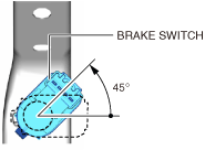
Brake Switch Installation Note
1. Inspect the brake pedal. (See BRAKE PEDAL INSPECTION [(E)].)
2. With the brake pedal fully released, insert the brake switch into the installation hole on the brake pedal.
3. Secure the brake switch by turning it counterclockwise 45°.
am3zzw00025057
|