 |
am3zzw00031911
ON/OFF SOLENOID REMOVAL/INSTALLATION [ET6A-EL, ET6AX-EL (E)]
id0517n31171y3
Replacement Part
|
Bolt
Quantity: 16
Location of use: Oil pan
|
Oil and Chemical Type
|
Sealant
Type: TB1217E or equivalent
|
1. Disconnect the negative battery terminal. (See NEGATIVE BATTERY TERMINAL DISCONNECTION/CONNECTION [(E)].)
2. Remove the front under cover No.2. (See FRONT UNDER COVER No.2 REMOVAL/INSTALLATION.)
3. Remove the front under cover No.1. (See FRONT UNDER COVER No.1 REMOVAL/INSTALLATION.)
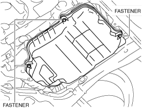
4. Remove the oil pan cover. (SKYACTIV-X 2.0)
am3zzw00031911
|
5. Clean the transaxle exterior throughout with a steam cleaner or cleaning solvents.
6. Drain the ATF. (See AUTOMATIC TRANSAXLE FLUID (ATF) REPLACEMENT [ET6A-EL, ET6AX-EL (E)].)
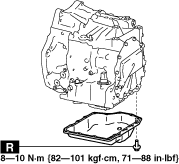
7. Remove the oil pan.
8. Disconnect the ON/OFF solenoid connector.
ac5uuw00000202
|
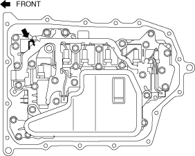
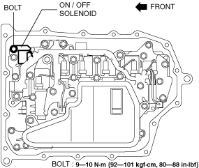
9. Remove the ON/OFF solenoid.
am3zzw00031535
|
10. Install the ON/OFF solenoid.
am3zzw00031535
|
11. Connect the ON/OFF solenoid connector.
ac5uuw00000202
|
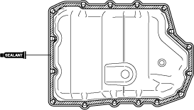
12. Apply a light coat of silicone sealant (TB1217E or equivalent) to the contact surfaces of the oil pan and transaxle case.
ac5uuw00000204
|
13. Install the oil pan with new bolts before the applied sealant starts to harden.
am3zzw00031534
|
14. Add the ATF. (See AUTOMATIC TRANSAXLE FLUID (ATF) REPLACEMENT [ET6A-EL, ET6AX-EL (E)].)
15. Install the oil pan cover. (SKYACTIV-X 2.0)
am3zzw00031911
|
16. Install the front under cover No.1. (See FRONT UNDER COVER No.1 REMOVAL/INSTALLATION.)
17. Install the front under cover No.2. (See FRONT UNDER COVER No.2 REMOVAL/INSTALLATION.)
18. Connect the negative battery terminal. (See NEGATIVE BATTERY TERMINAL DISCONNECTION/CONNECTION [(E)].)
19. Perform the “Mechanical System Test”. (See MECHANICAL SYSTEM TEST [ET6A-EL, ET6AX-EL (E)].)