|
1
|
VERIFY OTHER DTCs RELATED TO SEAT WARMER UNIT (RH) CIRCUIT
• Perform the DTC inspection for the dash-electrical supply unit.
• Are other DTCs related to the seat warmer unit (RH) circuit displayed?
|
Yes
|
Repair the malfunctioning location according to the applicable DTC troubleshooting.
|
|
No
|
Go to the next step.
|
|
2
|
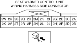
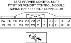
INSPECT SEAT WARMER CONTROL UNIT CONNECTOR FOR MALFUNCTION
• Inspect the applicable connector and terminal.
• Are the connector and terminal normal?
|
Yes
|
Go to the next step.
|
|
No
|
Repair or replace the malfunctioning location and perform the repair completion verification.
|
|
3
|
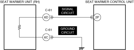
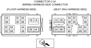
INSPECT CONNECTOR C-61 FOR MALFUNCTION
• Inspect the applicable connector and terminal.
• Are the connector and terminal normal?
|
Yes
|
Go to the next step.
|
|
No
|
Repair or replace the malfunctioning location and perform the repair completion verification.
|
|
4
|
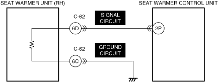
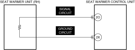
INSPECT SEAT WARMER UNIT (RH) SIGNAL CIRCUIT AND GROUND CIRCUIT FOR SHORT TO POWER SUPPLY
• Inspect the applicable circuit for a short to power supply.
• Is the circuit normal?
|
Yes
|
Go to the next step.
|
|
No
|
Repair or replace the malfunctioning location and perform the repair completion verification.
|
|
5
|
INSPECT SEAT WARMER UNIT (RH) FOR MALFUNCTION
• Install/connect the part removed/disconnected during the troubleshooting procedure.
• Switch the ignition off.
• Switch the ignition ON (engine off or on).
• With the seat warmer switch (RH) turned on, measure the resistance between the following terminals (vehicle wiring harness side).
-
― Connector C-61 terminal 6C
― Connector C-61 terminal 6D
• Does the resistance change with the elapse of time (temperature increase)?
|
Yes
|
Go to the next step.
|
|
No
|
Repair or replace the malfunctioning location, then go to the next step.
|
|
6
|
INSPECT SEAT WARMER CONTROL UNIT FOR MALFUNCTION DEPENDING ON REPEATABILITY
• Install/connect the part removed/disconnected during the troubleshooting procedure.
• Clear the DTC recorded in the memory.
• Perform the DTC inspection for the dash-electrical supply unit.
• Is the same Pending DTC present?
|
Yes
|
Refer to the controller area network (CAN) malfunction diagnosis flow to inspect for a CAN communication error.
If the CAN communication is normal, replace the malfunctioning location and perform the repair completion verification.
|
|
No
|
Go to repair completion verification 2.
|
|
Repair completion verification 1
|
VERIFY THAT VEHICLE IS REPAIRED
• Install/connect the part removed/disconnected during the troubleshooting procedure.
• Clear the DTC recorded in the memory.
• Perform the DTC inspection for the dash-electrical supply unit.
• Is the same Pending DTC present?
|
Yes
|
Refer to the controller area network (CAN) malfunction diagnosis flow to inspect for a CAN communication error.
If the CAN communication is normal, perform the diagnosis from Step 1.
• If the malfunction recurs, replace the dash-electrical supply unit, then go to the next step.
|
|
No
|
Go to the next step.
|
|
Repair completion verification 2
|
VERIFY IF OTHER DTCs DISPLAYED
• Perform the DTC inspection.
• Are any DTCs displayed?
|
Yes
|
Repair the malfunctioning location according to the applicable DTC troubleshooting.
|
|
No
|
DTC troubleshooting completed.
|