DTC B1227:11, B1227:13, B1227:87 OR B1227:96 [SAS CONTROL MODULE (STANDARD DEPLOYMENT CONTROL SYSTEM)]
id0802g7002000
Outline
System malfunction location |
B1227:11: Passenger-side pressure sensor circuit short to body ground B1227:13: Passenger-side pressure sensor circuit open circuit or short to power supply B1227:87: Signal reception error from passenger-side pressure sensor B1227:96: Passenger-side pressure sensor internal malfunction |
|
---|---|---|
Detection condition
|
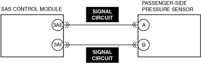
• Wiring harness between the passenger-side pressure sensor and SAS control module has a malfunction
• Passenger-side pressure sensor has a malfunction
|
|
Fail-safe
|
• Not applicable
|
|
Possible cause
|
• Passenger-side pressure sensor connector malfunction
• Open circuit in passenger-side pressure sensor signal circuit
• Short circuit to ground in passenger-side pressure sensor signal circuit
• Short circuit to power supply in passenger-side pressure sensor signal circuit
• Passenger-side pressure sensor malfunction
• SAS control module malfunction
|
|
![]() |
||
![]() |
![]() |
Diagnostic Procedure
Step |
Inspection |
Results |
Action |
---|---|---|---|
1
|
INSPECT PASSENGER-SIDE PRESSURE SENSOR CONNECTOR
• Switch the ignition off.
• Disconnect the negative battery terminal and wait for 1 min or more.
• Disconnect the passenger-side pressure sensor connector.
• Inspect the passenger-side pressure sensor connector (both sides of connector). (Corrosion, damage, and disconnected pins)
• Is there any malfunction of the passenger-side pressure sensor connector (wiring harness-side)?
|
Yes
|
Replace the malfunctioning part and perform the repair completion verification.
|
No
|
Go to the next step.
|
||
2
|
INSPECT PASSENGER-SIDE PRESSURE SENSOR SIGNAL CIRCUIT FOR SHORT TO GROUND
• Disconnect the driver-side knee air bag module connector.
• Disconnect the driver-side air bag module connectors.
• Remove the clock spring.
• Disconnect the passenger-side air bag module connector.
• Disconnect the driver and passenger-side side air bag module connectors.
• Disconnect the driver and passenger-side front seat connectors.
• Disconnect the driver and passenger-side curtain air bag module connectors.
• Disconnect the driver and passenger-side front pre-tensioner seat belt connectors.
• Disconnect the driver and passenger-side rear pre-tensioner seat belt connectors.
• Disconnect the all SAS control module connectors.
• Inspect the passenger-side pressure sensor signal circuit for short to ground.
(See CIRCUIT INSPECTION.)
• Is the circuit normal?
|
Yes
|
Go to the next step.
|
No
|
Repair or replace the malfunctioning location and perform the repair completion verification.
|
||
3
|
INSPECT PASSENGER-SIDE PRESSURE SENSOR SIGNAL CIRCUIT FOR OPEN CIRCUIT
• Passenger-side pressure sensor and SAS control module connectors are disconnected.
• Inspect the passenger-side pressure sensor signal circuit for open circuit.
(See CIRCUIT INSPECTION.)
• Is the circuit normal?
|
Yes
|
Go to the next step.
|
No
|
Repair or replace the malfunctioning location and perform the repair completion verification.
|
||
4
|
INSPECT PASSENGER-SIDE PRESSURE SENSOR SIGNAL CIRCUIT FOR SHORT TO POWER SUPPLY
• Passenger-side pressure sensor and SAS control module connectors are disconnected.
• Connect the negative battery terminal.
• Switch the ignition ON (engine off or on).
• Inspect the passenger-side pressure sensor signal circuit for short to power supply.
(See CIRCUIT INSPECTION.)
• Is the circuit normal?
|
Yes
|
Replace the passenger-side pressure sensor and perform the repair completion verification.
|
No
|
Repair or replace the malfunctioning location and perform the repair completion verification.
|
||
Repair completion verification
|
PERFORM SAS CONTROL MODULE DTC INSPECTION
• Switch the ignition off.
• Disconnect the negative battery terminal and wait for 1 min or more.
• Connect the SAS control module connectors.
• Reconnect all disconnected connectors.
• Connect the negative battery terminal.
• Switch the ignition ON (engine off or on).
• Clear the DTC for the SAS control module using the M-MDS.
(See CLEARING DTC.)
• Perform the DTC inspection for the SAS control module using the M-MDS.
(See DTC INSPECTION.)
• Are the same Pending DTCs present?
|
Yes
|
Refer to the controller area network (CAN) malfunction diagnosis flow to inspect for a CAN communication error.
If the CAN communication is normal, perform the diagnosis from Step 1.
• If the malfunction recurs, replace the SAS control module.
|
No
|
DTC troubleshooting completed.
|