|
1
|
INSPECT DRIVER-SIDE KNEE AIR BAG MODULE CONNECTOR
-
Warning
-
• Handling the component parts improperly can accidentally operate (deploy) the air bag module, which may seriously injure you. Read the service warnings/cautions and the workshop manual before handling the air bag system components.
• Switch the ignition off.
• Disconnect the negative battery terminal and wait for 1 min or more.
• Disconnect the driver-side knee air bag module connector.
• Inspect the driver-side knee air bag module connector (both sides of connector). (Corrosion, damage, and disconnected pins)
• Is there any malfunction of the driver-side knee air bag module connector (wiring harness-side)?
|
Yes
|
Repair or replace the malfunctioning location and perform the repair completion verification.
|
|
No
|
Go to the next step.
|
|
2
|
INSPECT DRIVER-SIDE KNEE AIR BAG MODULE DEPLOYMENT SIGNAL CIRCUIT FOR SHORT TO GROUND
• Disconnect the driver-side air bag module connectors.
• Remove the clock spring.
• Disconnect the passenger-side air bag module connector.
• Disconnect the driver and passenger-side side air bag module connectors.
• Disconnect the driver and passenger-side front seat connectors.
• Disconnect the driver and passenger-side curtain air bag module connectors.
• Disconnect the driver and passenger-side front pre-tensioner seat belt connectors.
• Disconnect the driver and passenger-side rear pre-tensioner seat belt connectors.
• Disconnect the all SAS control module connectors.
• Inspect the driver-side knee air bag module deployment signal circuit for a short to ground.
-
Note
-
• Inspect for a short to ground while shaking the wiring harness between the SAS control module and driver-side knee air bag module.
• Is the circuit normal?
|
Yes
|
Go to the next step.
|
|
No
|
Repair or replace the malfunctioning location and perform the repair completion verification.
|
|
3
|
INSPECT DRIVER-SIDE KNEE AIR BAG MODULE DEPLOYMENT SIGNAL CIRCUIT FOR OPEN CIRCUIT
• Driver-side knee air bag module and SAS control module connectors are disconnected.
• Inspect the driver-side knee air bag module deployment signal circuit for open circuit.
-
Note
-
• Inspect for open circuit while shaking the wiring harness between the SAS control module and driver-side knee air bag module.
• Is the circuit normal?
|
Yes
|
Go to the next step.
|
|
No
|
Repair or replace the malfunctioning location and perform the repair completion verification.
|
|
4
|
INSPECT DRIVER-SIDE KNEE AIR BAG MODULE DEPLOYMENT SIGNAL CIRCUIT FOR SHORT TO EACH OTHER
• Driver-side knee air bag module and SAS control module connectors are disconnected.
• Inspect the driver-side knee air bag module deployment signal circuit for short to each other.
-
Note
-
• Inspect for short to each other while shaking the wiring harness between the SAS control module and driver-side knee air bag module.
• Is the circuit normal?
|
Yes
|
Go to the next step.
|
|
No
|
Repair or replace the malfunctioning location and perform the repair completion verification.
|
|
5
|
INSPECT DRIVER-SIDE KNEE AIR BAG MODULE DEPLOYMENT SIGNAL CIRCUIT FOR SHORT TO OTHER AIR BAG MODULE CIRCUIT
• Driver-side knee air bag module and SAS control module connectors are disconnected.
• Other air bag module and pre-tensioner seat belt connectors are disconnected.
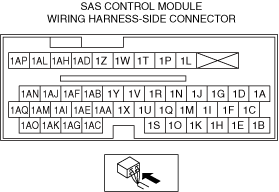
• Refer to the wiring diagram and inspect for continuity between the following terminals and other air bag module/pre-tensioner seat belt terminals (wiring harness-side).
-
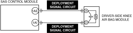
― SAS control module terminal 1AI
― SAS control module terminal 1AE
-
Note
-
• Inspect for continuity while shaking the wiring harness between the SAS control module and driver-side knee air bag module.
• Is there continuity?
|
Yes
|
Repair or replace the malfunctioning location and perform the repair completion verification.
|
|
No
|
Go to the next step.
|
|
6
|
INSPECT DRIVER-SIDE KNEE AIR BAG MODULE DEPLOYMENT SIGNAL CIRCUIT FOR SHORT TO POWER SUPPLY
• Driver-side knee air bag module and SAS control module connectors are disconnected.
• Connect the negative battery terminal.
• Switch the ignition ON (engine off or on).
• Inspect the driver-side knee air bag module deployment signal circuit for a short to power supply.
-
Note
-
• Inspect for a short to power supply while shaking the wiring harness between the SAS control module and driver-side knee air bag module.
• Is the circuit normal?
|
Yes
|
Go to the next step.
|
|
No
|
Repair or replace the malfunctioning location and perform the repair completion verification.
|
|
7
|
INSPECT DRIVER-SIDE KNEE AIR BAG MODULE
• Disconnect the negative battery terminal and wait for 1 min or more.
• Connect the SAS control module connectors.
• Except for the driver-side knee air bag module connector, reconnect all disconnected connectors.
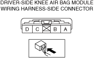
• Apply 2 ohms resistance to the driver-side knee air bag module terminals A and D (wiring harness-side).
• Connect the negative battery terminal.
• Switch the ignition ON (engine off or on).
• Clear the DTC for the SAS control module using the M-MDS.
• Perform the DTC inspection for the SAS control module using the M-MDS.
• Are the same Pending DTCs present?
|
Yes
|
Go to the next step.
|
|
No
|
Replace the driver-side knee air bag module and perform the repair completion verification.
|
|
Repair completion verification
|
PERFORM SAS CONTROL MODULE DTC INSPECTION
• Switch the ignition off.
• Disconnect the negative battery terminal and wait for 1 min or more.
• Disconnect the 2 ohms resistance.
• Connect the driver-side knee air bag module connector.
• Connect the negative battery terminal.
• Switch the ignition ON (engine off or on).
• Clear the DTC for the SAS control module using the M-MDS.
• Perform the DTC inspection for the SAS control module using the M-MDS.
• Are the same Pending DTCs present?
|
Yes
|
Refer to the controller area network (CAN) malfunction diagnosis flow to inspect for a CAN communication error.
If the CAN communication is normal, perform the diagnosis from Step 1.
• If the malfunction recurs, replace the SAS control module.
|
|
No
|
DTC troubleshooting completed.
|