 |
am3zzw00038219
RETRACT/RETURN MOTOR REMOVAL/INSTALLATION
id091200052200
Replacement part
|
Cover
Quantity: 1
Location of use: Power outer mirror
|
Tape
Quantity: 1
Location of use: Power outer mirror
|
Push nut
Quantity: 1
Location of use: Power outer mirror
|
|
Seal packing
Quantity: 1
Location of use: Power outer mirror
|
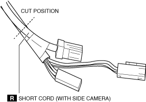
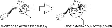
Short cord (With side camera)
Quantity: 1
Location of use: Power outer mirror
|
Side camera connector cover (With side camera)
Quantity: 1
Location of use: Power outer mirror
|
1. Perform the front door glass preparation. (See FRONT DOOR GLASS REMOVAL/INSTALLATION.)
2. Disconnect the negative battery terminal. (See NEGATIVE BATTERY TERMINAL DISCONNECTION/CONNECTION [(E)].)
3. Remove the following parts:
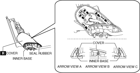
4. Remove the seal rubber from the inner base.
am3zzw00038219
|
5. Detach the inner base tabs from the cover.
6. Remove the cover.
7. Remove the following parts:
am3zzw00038208
|
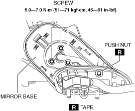
8. Remove the mirror base. (See Mirror Base Installation Note.)
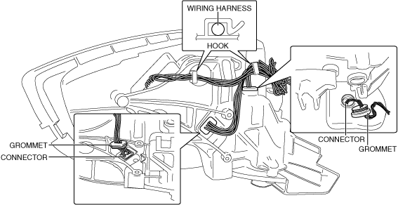
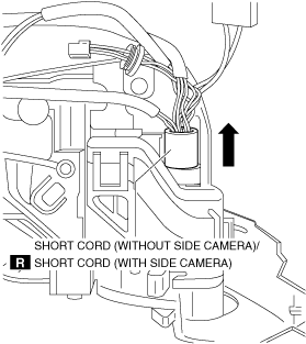
9. Perform the following procedure to pull the short cord out of the power outer mirror.
am3zzw00038174
|
am3zzw00038175
|
ac30zw00005185
|
am3zzw00038209
|
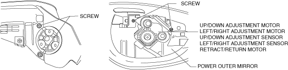
10. Remove the screws.
am3zzw00038210
|
11. Remove the following parts from the power outer mirror as a single unit.
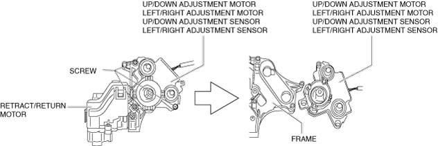
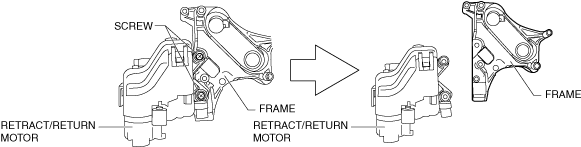
12. Remove the screws.
am3zzw00038215
|
13. Remove the following parts from the frame as a single unit.
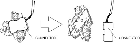
14. Disconnect the connector.
am3zzw00038211
|
15. Remove the screws.
am3zzw00038178
|
16. Remove the retract/return motor from the frame.
17. Install in the reverse order of removal.
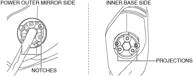
Mirror Base Installation Note
1. Align the mirror base projections with the power outer mirror notches.
am3zzw00038212
|
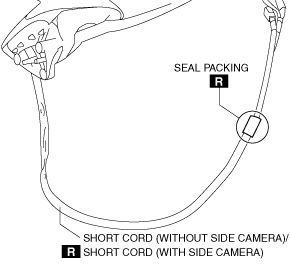
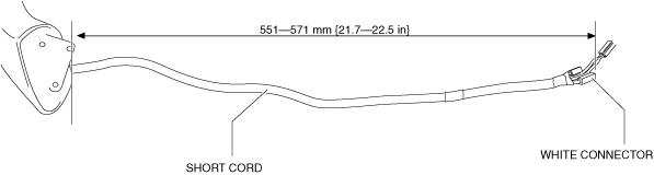
Seal Packing Installation Note
1. Verify that the length of the short cord is the length shown in the figure.
ac30zw00005183
|
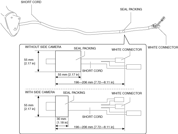
2. Install the seal packing to the short cord at the position shown in the figure.
ac30zw00005184
|
Side Camera Connector Cover Installation Note
1. Install the side camera connector cover to the short cord. (See ELECTRICAL SYSTEM [(E)].)
am3zzw00038180
|