 |
ac30zw00004986
FUEL GAUGE SENDER UNIT INSPECTION [(E)]
id0922000121x2
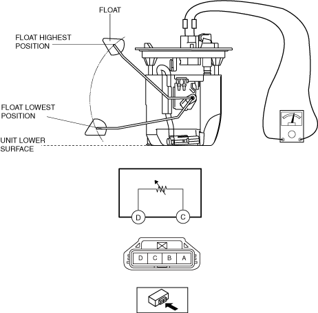
Fuel gauge sender unit connector 4-pin type
1. Perform the "Fuel Line Safety Procedure" referring to the "BEFORE SERVICE PRECAUTION".
(See BEFORE SERVICE PRECAUTION [SKYACTIV-G (WITHOUT CYLINDER DEACTIVATION (E))])
2. If the fuel gauge level indicates 8/16 or more, refer to the "FUEL DRAINING PROCEDURE" and drain the fuel.
(See FUEL DRAINING PROCEDURE [SKYACTIV-G (WITHOUT CYLINDER DEACTIVATION (E))])
3. Disconnect the negative battery terminal. (See NEGATIVE BATTERY TERMINAL DISCONNECTION/CONNECTION [(E)].)
4. Remove the fuel gauge sender unit. (See FUEL GAUGE SENDER UNIT REMOVAL/INSTALLATION [(E)].)
5. Verify that the resistance at fuel gauge sender unit terminals D and C is as follows according to the height of the float.
ac30zw00004986
|
Fuel gauge sender unit connector 5-pin type
1. Perform the "Fuel Line Safety Procedure" referring to the "BEFORE SERVICE PRECAUTION".
(See BEFORE SERVICE PRECAUTION [SKYACTIV-G (WITHOUT CYLINDER DEACTIVATION (E))])
2. If the fuel gauge level indicates 8/16 or more, refer to the "FUEL DRAINING PROCEDURE" and drain the fuel.
(See FUEL DRAINING PROCEDURE [SKYACTIV-G (WITHOUT CYLINDER DEACTIVATION (E))])
3. Disconnect the negative battery terminal. (See NEGATIVE BATTERY TERMINAL DISCONNECTION/CONNECTION [(E)].)
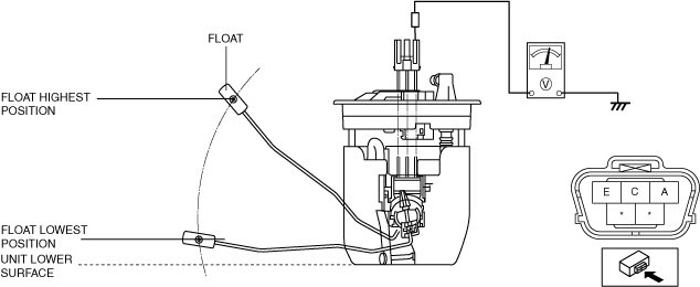
4. Apply 5 V to fuel gauge sender unit terminals A.
5. Verify the voltage of fuel gauge sender unit terminal E.
am3zzw00020163
|
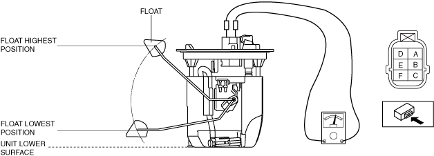
Fuel gauge sender unit connector 6-pin type
1. Perform the "Fuel Line Safety Procedure" referring to the "BEFORE SERVICE PRECAUTION".
(See BEFORE SERVICE PRECAUTION [SKYACTIV-G (WITHOUT CYLINDER DEACTIVATION (E))])
2. If the fuel gauge level indicates 8/16 or more, refer to the "FUEL DRAINING PROCEDURE" and drain the fuel.
(See FUEL DRAINING PROCEDURE [SKYACTIV-G (WITHOUT CYLINDER DEACTIVATION (E))])
3. Disconnect the negative battery terminal. (See NEGATIVE BATTERY TERMINAL DISCONNECTION/CONNECTION [(E)].)
4. Remove the fuel gauge sender unit. (See FUEL GAUGE SENDER UNIT REMOVAL/INSTALLATION [(E)].)
5. Verify that the resistance at fuel gauge sender unit terminals F and C is as follows according to the height of the float.
am3zzw00030141
|
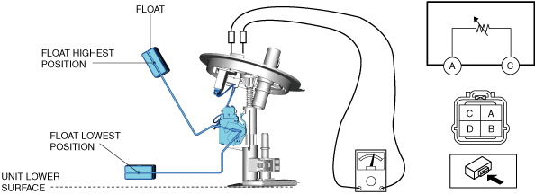
Fuel gauge sender unit [AWD (sub)]
1. Perform the "Fuel Line Safety Procedure" referring to the "BEFORE SERVICE PRECAUTION".
(See BEFORE SERVICE PRECAUTION [SKYACTIV-G (WITHOUT CYLINDER DEACTIVATION (E))])
2. If the fuel gauge level indicates 8/16 or more, refer to the "FUEL DRAINING PROCEDURE" and drain the fuel.
(See FUEL DRAINING PROCEDURE [SKYACTIV-G (WITHOUT CYLINDER DEACTIVATION (E))])
3. Disconnect the negative battery terminal. (See NEGATIVE BATTERY TERMINAL DISCONNECTION/CONNECTION [(E)].)
4. Remove the fuel gauge sender unit (sub). (See FUEL GAUGE SENDER UNIT REMOVAL/INSTALLATION [(E)].)
5. Verify that the resistance at fuel gauge sender unit terminals A and C is as follows according to the height of the float.
am3zzw00031701
|