1. : Mazda SST number
2. : Global SST number
1: 49 UN31 0123
2: 310–123
wrench

1: 49 JP02 002
2: –
Lock ring wrench

FUEL GAUGE SENDER UNIT REMOVAL/INSTALLATION [(E)]
id0922000120x2
Special Service Tool (SST)
|
1. : Mazda SST number
2. : Global SST number
|
|||
|
1: 49 UN31 0123
2: 310–123
wrench
|
|
1: 49 JP02 002
2: –
Lock ring wrench
|
|
Replacement part
|
Packing
Quantity: 1
Location of use: Fuel gauge sender unit (main (SKYACTIV-D))
|
Packing
Quantity: 1
Location of use: Fuel gauge sender unit (sub)
|
Retainer
Quantity: 1
Location of use: Quick Release Connector (sub)
|
Oil and Chemical Type
|
Engine oil
Type: Recommended oil
|
Fuel Gauge Sender Unit (Main)
SKYACTIV-G, SKYACTIV-X
SKYACTIV-D
1. Complete the “BEFORE SERVICE PRECAUTION”. (See BEFORE SERVICE PRECAUTION [SKYACTIV-D 1.8].)
2. Disconnect the negative battery terminal. (See NEGATIVE BATTERY TERMINAL DISCONNECTION/CONNECTION [(E)].)
3. Remove the rear seat cushion. (See REAR SEAT CUSHION REMOVAL/INSTALLATION.)
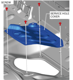
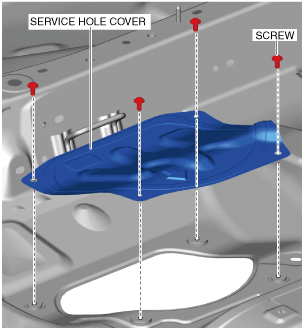
4. Remove the screws.
ac30zw00003097
|
5. Remove the service hole cover.
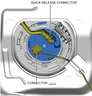
6. Disconnect the connector.
ac30zw00003757
|
7. Disconnect the quick release connector. (See QUICK RELEASE CONNECTOR (EMISSION SYSTEM) REMOVAL/INSTALLATION [SKYACTIV-D 1.8].)
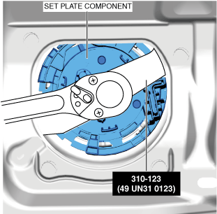
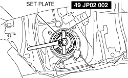
8. Install the SST shown in the figure.
ac30zw00003099
|
9. Remove the set plate component using the SST. (See Set plate component Installation Note (fuel gauge sender unit (main)).)
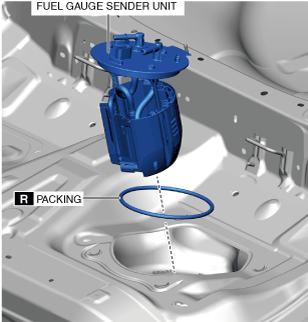
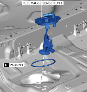
10. Remove the fuel gauge sender unit and packing.
ac30zw00003100
|
11. Install in the reverse order of removal.
12. Complete the “AFTER SERVICE PRECAUTION”. (See AFTER SERVICE PRECAUTION [SKYACTIV-D 1.8].)
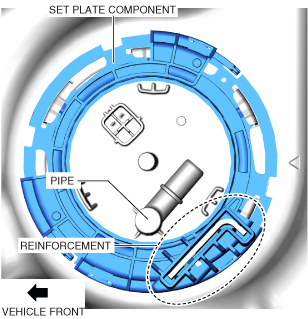
Set plate component Installation Note (fuel gauge sender unit (main))
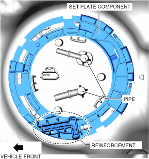
1. Align the reinforcement part of the set plate component near the pipe area of the fuel pump unit as shown in the figure and assemble.
ac30zw00003110
|
Fuel Gauge Sender Unit (Sub)
1. Complete the “BEFORE SERVICE PRECAUTION”. (See BEFORE SERVICE PRECAUTION [SKYACTIV-G (WITH CYLINDER DEACTIVATION (E))].) (See BEFORE SERVICE PRECAUTION [SKYACTIV-G (WITHOUT CYLINDER DEACTIVATION (E))].) (See BEFORE SERVICE PRECAUTION [SKYACTIV-X 2.0].) (See BEFORE SERVICE PRECAUTION [SKYACTIV-D 1.8].)
2. Disconnect the negative battery terminal. (See NEGATIVE BATTERY TERMINAL DISCONNECTION/CONNECTION [(E)].)
3. Remove the rear seat cushion. (See REAR SEAT CUSHION REMOVAL/INSTALLATION.)
4. Remove the screws.
ac30zw00003101
|
5. Remove the service hole cover.
6. Disconnect the connector.
ac30zw00003102
|
7. Disconnect the quick release connector. (See QUICK RELEASE CONNECTOR (EMISSION SYSTEM) REMOVAL/INSTALLATION [SKYACTIV-G (WITH CYLINDER DEACTIVATION (E))].) (See QUICK RELEASE CONNECTOR (EMISSION SYSTEM) REMOVAL/INSTALLATION [SKYACTIV-G (WITHOUT CYLINDER DEACTIVATION (E))].) (See QUICK RELEASE CONNECTOR (EMISSION SYSTEM) REMOVAL/INSTALLATION [SKYACTIV-X 2.0].) (See QUICK RELEASE CONNECTOR (EMISSION SYSTEM) REMOVAL/INSTALLATION [SKYACTIV-D 1.8].)
8. Install the SST shown in the figure.
ac30zw00004025
|
9. Remove the set plate component using the SST. (See Set plate component installation note (fuel gauge sender unit (sub)).)
10. Remove the fuel gauge sender unit and packing.
ac30zw00003104
|
11. Install in the reverse order of removal.
12. Complete the “AFTER SERVICE PRECAUTION”. (See AFTER SERVICE PRECAUTION [SKYACTIV-G (WITH CYLINDER DEACTIVATION (E))].) (See AFTER SERVICE PRECAUTION [SKYACTIV-G (WITHOUT CYLINDER DEACTIVATION (E))].) (See AFTER SERVICE PRECAUTION [SKYACTIV-X 2.0].) (See AFTER SERVICE PRECAUTION [SKYACTIV-D 1.8].)
Set plate component installation note (fuel gauge sender unit (sub))
1. Align the reinforcement part of the set plate component near the pipe area of the fuel pump unit as shown in the figure and assemble.
ac30zw00003109
|