 |
ac5wzw00010265
INDICATOR UNIT INSPECTION
id092200037600
Terminal Voltage Inspection
1. Disconnect the negative battery terminal. (See NEGATIVE BATTERY TERMINAL DISCONNECTION/CONNECTION [(E)])
2. Remove the sensor cover.(See SENSOR COVER REMOVAL/INSTALLATION.)
3. Connect the negative battery terminal. (See NEGATIVE BATTERY TERMINAL DISCONNECTION/CONNECTION [(E)])
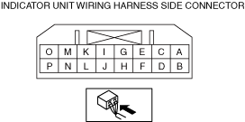
4. Verify that the voltages of each of the terminals are as indicated in the terminal voltage table (reference).
Terminal Voltage Table (Reference)
ac5wzw00010265
|
|
Terminal |
Signal name |
Connected to |
Measurement conditions |
Voltage (V) |
Inspection item(s) |
|
|---|---|---|---|---|---|---|
|
A
|
Power supply (IG1)
|
IG1 relay
|
Ignition switch ON (engine off or on)
|
B+
|
• F47 15A fuse
• IG1 relay
• Related wiring harness
|
|
|
Ignition switch off or ACC
|
1.0 or less
|
|||||
|
B
|
—
|
—
|
—
|
—
|
—
|
|
|
C
|
IG_DCDC
|
IG1 relay
|
Ignition switch ON (engine off or on)
|
B+
|
• F47 15A fuse
• Ignition relay (IG1_STAB)
• Related wiring harness
|
|
|
Ignition switch off or ACC
|
1.0 or less
|
|||||
|
D
|
Reverse
|
Auto dimming rearview mirror
|
R position
|
B+
|
• Auto dimming rearview mirror
• Related wiring harness
|
|
|
E
|
—
|
—
|
—
|
—
|
—
|
|
|
F
|
Ground
|
Body ground
|
Under any condition
|
Approx. 0
|
• GND point
• Related wiring harness
|
|
|
G
|
LIN_CBCM
|
BCM
|
Because this terminal is for communication, determination using terminal voltage inspection is not possible.
|
|||
|
H
|
—
|
—
|
—
|
—
|
—
|
|
|
I
|
—
|
—
|
—
|
—
|
—
|
|
|
J
|
—
|
—
|
—
|
—
|
—
|
|
|
K
|
—
|
—
|
—
|
—
|
—
|
|
|
L
|
—
|
—
|
—
|
—
|
—
|
|
|
M
|
—
|
—
|
—
|
—
|
—
|
|
|
N
|
—
|
—
|
—
|
—
|
—
|
|
|
O
|
—
|
—
|
—
|
—
|
—
|
|
|
P
|
—
|
—
|
—
|
—
|
—
|
|