Home DOOR-ELECTRICAL SUPPLY UNIT REMOVAL/INSTALLATION
id094000004400
1. Disconnect the negative battery terminal. (See NEGATIVE BATTERY TERMINAL DISCONNECTION/CONNECTION [(E)]
2. Remove the following parts:
(1) Inner garnish (See INNER GARNISH REMOVAL/INSTALLATION
(2) Power window main switch (See POWER WINDOW MAIN SWITCH REMOVAL/INSTALLATION
(3) Front door trim (See FRONT DOOR TRIM REMOVAL/INSTALLATION [(E)]
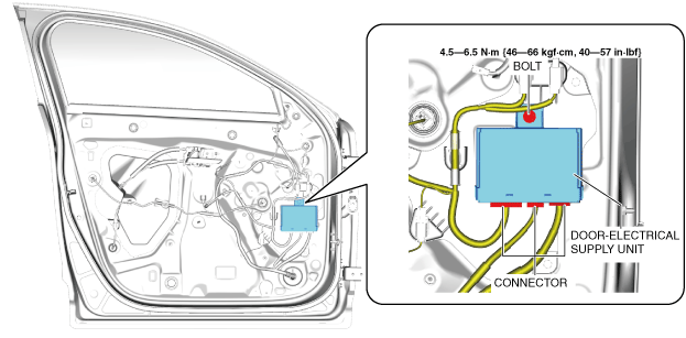
3. Disconnect the connectors.
4. Remove the bolt.
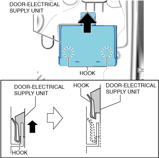
5. Lift up the door-electrical supply unit in the direction of the arrow shown in the figure and pull out the hooks from the service hole cover.
6. Remove the door-electrical supply unit.
7. Install in the reverse order of removal.
8. If the door-electrical supply unit (driver's side) is replaced, perform the following procedure.
(1) Switch the ignition ON (engine off) to complete the global central configuration (GCC) for the door-electrical supply unit (driver's side).
(2) Switch the ignition OFF.
(3) Switch the ignition ON (engine off or on) again.
(4) Clear the position memory system memory using the M-MDS. (With position memory system) (See POSITION MEMORY SYSTEM MEMORY CLEARING
(5) Switch the ignition ON (engine on) and wait for 1 s or more to complete the synchronization between the door-electrical supply unit (driver's side) and the following parts.
• Body control module (BCM)
• Electrical supply unit (ESU)
• Door-electrical supply unit (passenger's side)
(6) Switch the main power OFF.
(7) Perform the power window system initial setting. (See POWER WINDOW SYSTEM INITIALIZATION PROCEDURE
(8) Clear the DTC. (See CLEARING DTC
1. Disconnect the negative battery terminal. (See NEGATIVE BATTERY TERMINAL DISCONNECTION/CONNECTION [(E)]
2. Remove the following parts:
(1) Inner garnish (See INNER GARNISH REMOVAL/INSTALLATION
(2) Power window subswitch (See POWER WINDOW SUBSWITCH REMOVAL/INSTALLATION
(3) Front door trim (See FRONT DOOR TRIM REMOVAL/INSTALLATION [(E)]
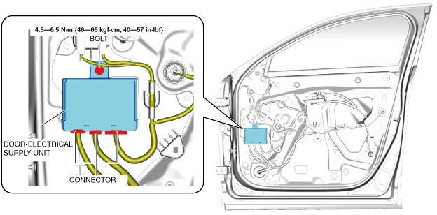
3. Disconnect the connectors.
4. Remove the bolt.
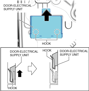
5. Lift up the door-electrical supply unit in the direction of the arrow shown in the figure and pull out the hooks from the service hole cover.
6. Remove the door-electrical supply unit.
7. Install in the reverse order of removal.
8. If the door-electrical supply unit (passenger's side) is replaced, perform the following procedure.
(1) Switch the ignition ON (engine off) to complete the global central configuration (GCC) for the door-electrical supply unit (passenger's side).
(2) Switch the ignition OFF.
(3) Switch the ignition ON (engine off or on) again.
(4) Clear the position memory system memory using the M-MDS. (With position memory system) (See POSITION MEMORY SYSTEM MEMORY CLEARING
(5) Switch the ignition ON (engine on) and wait for 1 s or more to complete the synchronization between the door-electrical supply unit (passenger's side) and the following parts.
• Body control module (BCM)
• Electrical supply unit (ESU)
• Door-electrical supply unit (driver's side)
(6) Switch the main power OFF.
(7) Perform the power window system initial setting. (See POWER WINDOW SYSTEM INITIALIZATION PROCEDURE
(8) Clear the DTC. (See CLEARING DTC