 |
am3zzw00027508
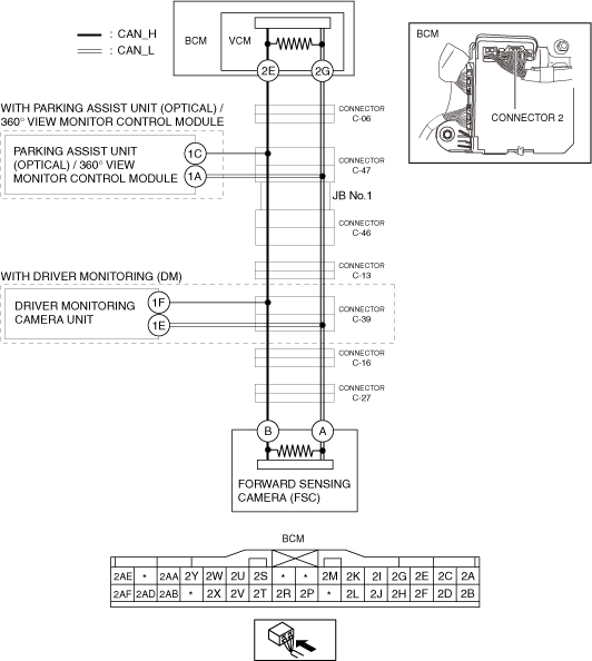
DETERMINING SHORT TO POWER SUPPLY LOCATION (CAN-BUS No.5) [(E)]
id1002x2003500
System Wiring Diagram
am3zzw00027508
|
Determination Procedure
|
Step |
Inspection |
Action |
|
|---|---|---|---|
|
1
|
INSPECT CAN LINE BETWEEN BODY CONTROL MODULE (BCM) AND CONNECTOR C-06 FOR SHORT TO POWER SUPPLY
• Switch the ignition off.
• Disconnect the negative battery terminal.
• Disconnect the connector C-06.
• Connect the negative battery terminal.
• Switch the ignition ON (engine off).
• Measure the voltage at body control module (BCM) terminals 2E and 2G.
• Is the voltage between 1.5—3.5 V?
|
Yes
|
Go to Step 3.
|
|
No
|
Go to the next step.
|
||
|
2
|
INSPECT BODY CONTROL MODULE (BCM) FOR SHORT TO POWER SUPPLY
• Switch the ignition off.
• Disconnect the negative battery terminal.
• Disconnect the connector 2 which has body control module (BCM) terminals 2E and 2G.
• Connect the connector C-06.
• Connect the negative battery terminal.
• Switch the ignition ON (engine off).
• Measure the voltage at body control module (BCM) terminals 2E and 2G (wiring harness side).
• Is the voltage between 1.5—3.5 V?
|
Yes
|
Replace the body control module (BCM) because there is a short to the power supply in the body control module (BCM).
|
|
No
|
Repair or replace the wiring harness between the body control module (BCM) and connector C-06 because the wiring harness is shorted to the power supply.
|
||
|
3
|
INSPECT CAN LINE BETWEEN CONNECTOR C-47 AND CONNECTOR C-06 FOR SHORT TO POWER SUPPLY
• Switch the ignition off.
• Disconnect the negative battery terminal.
• Disconnect the connector C-47.
• Connect the connector C-06.
• Connect the negative battery terminal.
• Switch the ignition ON (engine off).
• Measure the voltage at body control module (BCM) terminals 2E and 2G.
• Is the voltage between 1.5—3.5 V?
|
Yes
|
Go to the next step.
|
|
No
|
Repair or replace the wiring harness between the connector C-47 and connector C-06 because the wiring harness is shorted to the power supply.
|
||
|
4
|
INSPECT CAN LINE BETWEEN PARKING ASSIST UNIT (OPTICAL) / 360° VIEW MONITORING CAMERA UNIT AND CONNECTOR C-47 FOR SHORT TO POWER SUPPLY
• Measure the voltage at parking assist unit (optical) / 360° view monitoring camera unit terminals 1C and 1A.
• Is the voltage between 1.5—3.5 V?
|
Yes
|
Go to Step 6.
|
|
No
|
Go to the next step.
|
||
|
5
|
INSPECT PARKING ASSIST UNIT (OPTICAL) / 360° VIEW MONITORING CAMERA UNIT FOR SHORT TO POWER SUPPLY
• Switch the ignition off.
• Disconnect the negative battery terminal.
• Disconnect the parking assist unit (optical) / 360° view monitoring camera unit connector.
• Connect the connector C-47.
• Connect the negative battery terminal.
• Switch the ignition ON (engine off).
• Measure the voltage at body control module (BCM) terminals 2E and 2G.
• Is the voltage between 1.5—3.5 V?
|
Yes
|
Replace the parking assist unit (optical) / 360° view monitoring camera unit because there is a short to the power supply in the parking assist unit (optical) / 360° view monitoring camera unit.
|
|
No
|
Repair or replace the wiring harness between the parking assist unit (optical) / 360° view monitoring camera unit and connector C-47 because the wiring harness is shorted to the power supply.
|
||
|
6
|
INSPECT JB No.1 FOR SHORT TO POWER SUPPLY
• Switch the ignition off.
• Disconnect the negative battery terminal.
• Disconnect the connector C-46.
• Connect the connector C-47.
• Connect the negative battery terminal.
• Switch the ignition ON (engine off).
• Measure the voltage at body control module (BCM) terminals 2E and 2G.
• Is the voltage between 1.5—3.5 V?
|
Yes
|
Go to the next step.
|
|
No
|
Replace the JB No.1 because there is a short to the power supply in the JB No.1.
|
||
|
7
|
INSPECT CAN LINE BETWEEN CONNECTOR C-13 AND CONNECTOR C-46 FOR SHORT TO POWER SUPPLY
• Switch the ignition off.
• Disconnect the negative battery terminal.
• Disconnect the connector C-13.
• Connect the connector C-46.
• Connect the negative battery terminal.
• Switch the ignition ON (engine off).
• Measure the voltage at body control module (BCM) terminals 2E and 2G.
• Is the voltage between 1.5—3.5 V?
|
Yes
|
Go to the next step.
|
|
No
|
Repair or replace the wiring harness between the connector C-13 and connector C-46 because the wiring harness is shorted to the power supply.
|
||
|
8
|
INSPECT CAN LINE BETWEEN CONNECTOR C-39 AND CONNECTOR C-13 FOR SHORT TO POWER SUPPLY
• Switch the ignition off.
• Disconnect the negative battery terminal.
• Disconnect the connector C-39.
• Connect the connector C-13.
• Connect the negative battery terminal.
• Switch the ignition ON (engine off).
• Measure the voltage at body control module (BCM) terminals 2E and 2G.
• Is the voltage between 1.5—3.5 V?
|
Yes
|
Go to the next step.
|
|
No
|
Repair or replace the wiring harness between the connector C-39 and connector C-13 because the wiring harness is shorted to the power supply.
|
||
|
9
|
INSPECT CAN LINE BETWEEN DRIVER MONITORING CAMERA UNIT AND CONNECTOR C-39 FOR SHORT TO POWER SUPPLY
• Measure the voltage at driver monitoring camera unit terminals 1F and 1E.
• Is the voltage between 1.5—3.5 V?
|
Yes
|
Go to Step 11.
|
|
No
|
Go to the next step.
|
||
|
10
|
INSPECT DRIVER MONITORING CAMERA UNIT FOR SHORT TO POWER SUPPLY
• Switch the ignition off.
• Disconnect the negative battery terminal.
• Disconnect the driver monitoring camera unit connector.
• Connect the connector C-39.
• Connect the negative battery terminal.
• Switch the ignition ON (engine off).
• Measure the voltage at body control module (BCM) terminals 2E and 2G.
• Is the voltage between 1.5—3.5 V?
|
Yes
|
Replace the driver monitoring camera unit because there is a short to the power supply in the driver monitoring camera unit.
|
|
No
|
Repair or replace the wiring harness between the driver monitoring camera unit and connector C-39 because the wiring harness is shorted to the power supply.
|
||
|
11
|
INSPECT CAN LINE BETWEEN CONNECTOR C-16 AND CONNECTOR C-39 FOR SHORT TO POWER SUPPLY
• Switch the ignition off.
• Disconnect the negative battery terminal.
• Disconnect the connector C-16.
• Connect the connector C-39.
• Connect the negative battery terminal.
• Switch the ignition ON (engine off).
• Measure the voltage at body control module (BCM) terminals 2E and 2G.
• Is the voltage between 1.5—3.5 V?
|
Yes
|
Go to the next step.
|
|
No
|
Repair or replace the wiring harness between the connector C-16 and connector C-39 because the wiring harness is shorted to the power supply.
|
||
|
12
|
INSPECT CAN LINE BETWEEN CONNECTOR C-27 AND CONNECTOR C-16 FOR SHORT TO POWER SUPPLY
• Switch the ignition off.
• Disconnect the negative battery terminal.
• Disconnect the connector C-27.
• Connect the connector C-16.
• Connect the negative battery terminal.
• Switch the ignition ON (engine off).
• Measure the voltage at body control module (BCM) terminals 2E and 2G.
• Is the voltage between 1.5—3.5 V?
|
Yes
|
Go to the next step.
|
|
No
|
Repair or replace the wiring harness between the connector C-27 and connector C-16 because the wiring harness is shorted to the power supply.
|
||
|
13
|
INSPECT DRIVER FORWARD SENSING CAMERA (FSC) FOR SHORT TO POWER SUPPLY
• Switch the ignition off.
• Disconnect the negative battery terminal.
• Disconnect the forward sensing camera (FSC) connector.
• Connect the connector C-27.
• Connect the negative battery terminal.
• Switch the ignition ON (engine off).
• Measure the voltage at body control module (BCM) terminals 2E and 2G.
• Is the voltage between 1.5—3.5 V?
|
Yes
|
Replace the forward sensing camera (FSC) because there is a short to the power supply in the forward sensing camera (FSC).
|
|
No
|
Repair or replace the wiring harness between the forward sensing camera (FSC) and connector C-27 because the wiring harness is shorted to the power supply.
|
||