Home

Mazdamanuals.com

360°VIEW MONITOR CONTROL MODULE REMOVAL/INSTALLATION [(E)]

360°VIEW MONITOR CONTROL MODULE REMOVAL/INSTALLATION [(E)]


id1520000100x2

1.  Remove the head restraint.

2.  Remove the front seat installation bolts. (See FRONT SEAT REMOVAL/INSTALLATION [(E)].)

3.  Remove the front seat belt lower anchor.(See FRONT SEAT BELT REMOVAL/INSTALLATION.)

4.  Perform the following procedure. (without Mazda M Hybrid)

(1)  Switch the ignition off.
(2)  Disconnect the negative battery terminal and wait for 1 min or more. (See NEGATIVE BATTERY TERMINAL DISCONNECTION/CONNECTION [(E)].)

5.  Perform the following procedure. (with Mazda M Hybrid, without seat warmer system)

(1)  Switch the ignition off.
(2)  Disconnect the negative battery terminal and wait for 1 min or more. (See NEGATIVE BATTERY TERMINAL DISCONNECTION/CONNECTION [(E)].)

6.  Perform the following procedure. (with Mazda M Hybrid, with seat warmer system)

(1)  Verify if the ground plate needs to be disconnected and if it does, disconnect it. (See GROUND PLATE DISCONNECTION/CONNECTION.)

7.  Remove the front seat (LH). (See FRONT SEAT REMOVAL/INSTALLATION [(E)].)

8.  Remove the fasteners.

ac30zw00000735

9.  Remove the cover.

10.  Remove the bolts.

ac30zw00000736

11.  Perform the following procedure to allow the backup power supply to deplete its stored power. (With backup power supply).

Note
•  While the power stored in the backup power supply is being depleted, the door latch and lock actuator does not operate. This does not indicate an improper procedure. Continue to perform the procedure.
•  After performing Step (3) and the door latch and lock actuator starts to operate, the door lock switch (driver's side) no longer needs to be operated.
(1)  Close the front door (driver's side).
(2)  Open the front door (driver's side).
(3)  Within 30 s after performing Step (2), press and hold the unlock side of the door lock switch (driver's side) for 5 s or more.
(4)  Wait until the door latch and lock actuator stops.

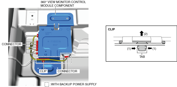
12.  Disconnect the connectors.

ac30zw00000737

13.  Remove the clip. (with backup power supply)

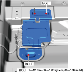
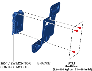
14.  Remove the 360° view monitor control module component.

15.  Remove the bolts.

am3zzw00022259

16.  Remove the bracket.

•  When replacing the bracket, remove the backup power supply. (with backup power supply) (See BACKUP POWER SUPPLY REMOVAL/INSTALLATION [(E)].)

17.  Remove the 360° view monitor control module.

18.  Install in the reverse order of removal.

19.  If the 360° view monitor control module is replaced, perform the following procedure.

(1)  Switch the ignition ON (engine off) and wait for 5 s or more to complete the global central configuration (GCC) for the 360° view monitor control module.
(2)  Switch the ignition OFF and wait for 5 s or more.
(3)  Switch the ignition ON (engine off) again and wait for 5 s or more.
(4)  Clear the DTC. (See CLEARING DTC.)
(5)  Perform the 360° view monitor system aiming. (See 360°VIEW MONITOR SYSTEM AIMING.)