Home

Mazdamanuals.com

GROUND PLATE DISCONNECTION/CONNECTION

GROUND PLATE DISCONNECTION/CONNECTION


id144200001200

Caution
•  When servicing the following parts, disconnect the ground plate. Otherwise, the Mazda M Hybrid related parts could be damaged. (See Ground Plate Disconnection/Connection.)
―  Integrated starter generator (ISG)
―  DC-DC converter (Mazda M Hybrid)
―  Seat warmer control unit (With seat warmer system/without position memory system)
―  Position memory control module (With position memory system)
―  Front seat (driver's side) (With position memory system)
―  Front seat (passenger's seat) (With seat warmer system/without position memory system)
―  Relay and fuse block (With seat warmer system)
•  Do not store the ground plate while it is installed to the Mazda M Hybrid battery. If the ground plate is installed while the Mazda M Hybrid battery is malfunctioning (internal relay stuck), the insulation effect may not be obtained and could result in a short circuit.

Ground plate disconnection necessity verification procedure

1.  Perform the DTC inspection. (See DTC INSPECTION.)

•  If DTC P0AA1:00 is displayed, disconnect the ground plate. (See Ground Plate Disconnection/Connection.)

2.  Switch the ignition OFF.

3.  Disconnect the negative battery terminal and wait for 1 min or more. (See NEGATIVE BATTERY TERMINAL DISCONNECTION/CONNECTION [(E)].)

4.  Verify that voltage is not applied using a tester.

•  If voltage is applied, disconnect the ground plate. (See Ground Plate Disconnection/Connection.)
•  If the voltage is 1.0 V or less, it is not necessary to disconnect the ground plate.
am3zzw00034614


Ground Plate Disconnection/Connection

1.  Switch the ignition OFF.

2.  Disconnect the negative battery terminal and wait for 1 min or more. (See NEGATIVE BATTERY TERMINAL DISCONNECTION/CONNECTION [(E)].)

3.  Lift up the vehicle.

4.  Remove the following parts.

(1)  Tunnel cover (See EXHAUST SYSTEM REMOVAL/INSTALLATION [SKYACTIV-G (WITH CYLINDER DEACTIVATION (E))].)
(2)  Gusset (See FRONT CROSSMEMBER REMOVAL/INSTALLATION [(E)].)
(3)  Floor under cover No.1 (LH) (See FLOOR UNDER COVER REMOVAL/INSTALLATION.)

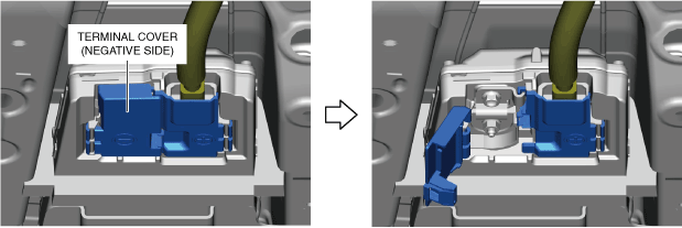
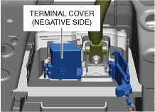
5.  Open the terminal cover (negative side).

am3zzw00031056

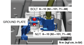
6.  Remove the nut and bolt shown in the figure and remove the ground plate.

am3zzw00031057

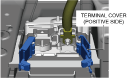
7.  Open the terminal cover (positive side).

am3zzw00031058

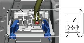
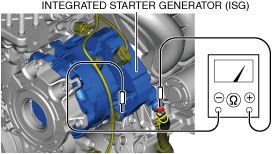
8.  Verify that the generation of voltage does not occur using a tester.

aaxjjw00023626

9.  Close the terminal cover (negative side).

am3zzw00031059

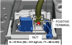
10.  Remove the nut shown in the figure and disconnect the positive terminal.

am3zzw00031060

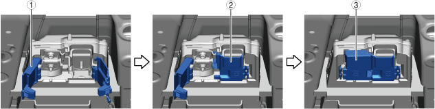
11.  Close the terminal cover using the following procedure.

(1)  Open the terminal cover (negative side).
aaxjjw00023629
(2)  Close the terminal cover (positive side).
(3)  Close the terminal cover (negative side).

12.  Connect in the reverse order of disconnection.