 |
ac30zw00002256
EXHAUST SYSTEM REMOVAL/INSTALLATION [SKYACTIV-G (WITH CYLINDER DEACTIVATION (E))]
id0115u3800200
Replacement Part
|
Gasket
Quantity: 1
Location of use: Main silencer
|
Nut
Quantity: 4
Location of use: TWC
|
Exhaust manifold gasket
Quantity: 1
Location of use: Exhaust manifold
|
|
Gasket
Quantity: 1
Location of use: Exhaust manifold
|
Nut
Quantity: 5
Location of use: Exhaust manifold (WU-TWC)
|
—
|
2WD
1. Disconnect the negative battery terminal. (See NEGATIVE BATTERY TERMINAL DISCONNECTION/CONNECTION [(E)].)
2. Remove the floor under cover No.1 (RH). (With Mazda M Hybrid) (See FLOOR UNDER COVER REMOVAL/INSTALLATION.)
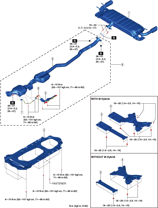
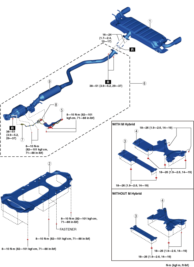
3. Remove in the order indicated in the table.
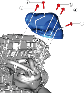
4. Remove the insulator. (See Exhaust Manifold Insulator Removal Note.)
5. Install in the reverse order of removal.
Step 1
ac30zw00002256
|
|
1
|
Main silencer
|
|
2
|
Tunnel cover
|
|
3
|
Brace bar
(See Brace Bar Installation Note.)
|
|
4
|
Tunnel member
|
|
5
|
Connector
|
|
6
|
TWC component
(See TWC component Removal Note.)
|
|
7
|
HO2S
|
|
8
|
Exhaust shutter valve connector
|
|
9
|
TWC
|
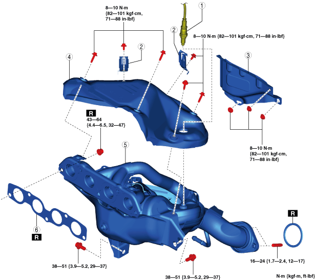
Step 2
ac30zw00002257
|
|
1
|
A/F sensor
|
|
2
|
Clip
|
|
3
|
Insulator
|
|
4
|
Exhaust manifold insulator
|
|
5
|
Exhaust manifold (WU-TWC)
|
|
6
|
Exhaust manifold gasket
|
Exhaust system insulator removal/installation
1. Remove the floor under cover No.1 (RH). (Without Mazda M Hybrid) (See FLOOR UNDER COVER REMOVAL/INSTALLATION.)
2. Remove the floor under cover No.2. (See FLOOR UNDER COVER REMOVAL/INSTALLATION.)
3. Remove the Mazda M hybrid battery. (With Mazda M Hybrid) (See Mazda M Hybrid BATTERY REMOVAL/INSTALLATION.)
4. Remove in the order indicated in the table.
5. Install in the reverse order of removal.
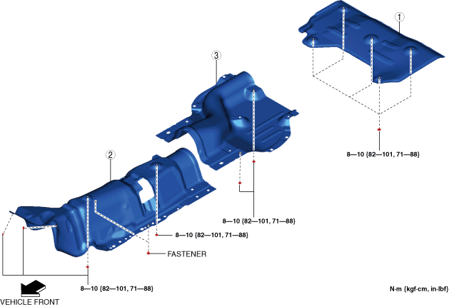
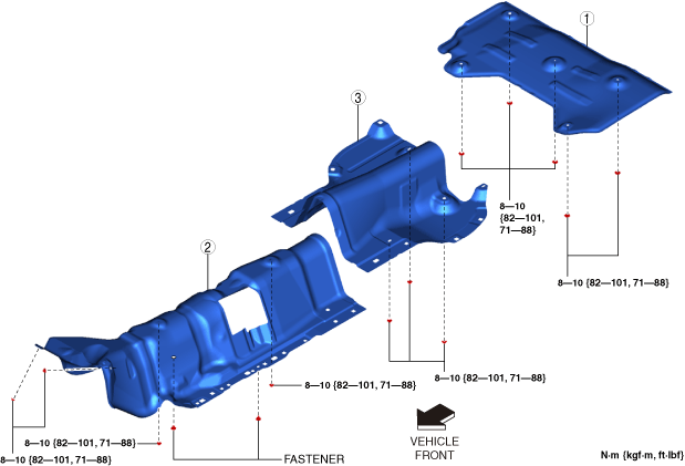
ac30zw00002258
|
|
1
|
Insulator (rear)
|
|
2
|
Insulator (front)
|
|
3
|
Insulator (middle)
|
TWC component Removal Note
1. Remove the floor under cover No.1 (LH). (See FLOOR UNDER COVER REMOVAL/INSTALLATION.)
2. Remove the TWC component.
Exhaust Manifold Insulator Removal Note
1. Remove the plug hole plate. (See PLUG HOLE PLATE REMOVAL/INSTALLATION [SKYACTIV-G (WITH CYLINDER DEACTIVATION (E))].)
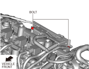
2. Remove the bolts shown in the figure. (See PURGE SOLENOID VALVE REMOVAL/INSTALLATION [SKYACTIV-G (WITH CYLINDER DEACTIVATION (E))].)
ac5wzw00010681
|
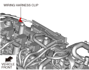
3. Disconnect the wiring harness clip shown in the figure.
ac5wzw00010682
|
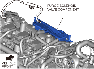
4. Set the purge solenoid valve component aside so that it does not interfere with the servicing.
ac5wzw00010695
|
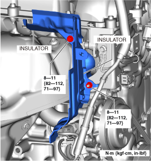
5. Remove the insulators shown in the figure.
am3zzw00031802
|
6. Remove the exhaust manifold insulator.
Exhaust Manifold Removal Note
1. Remove the front crossmember. (See FRONT CROSSMEMBER REMOVAL/INSTALLATION [(E)].)
2. Remove the exhaust manifold.
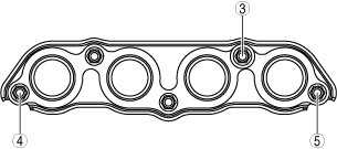
Exhaust Manifold Installation Note
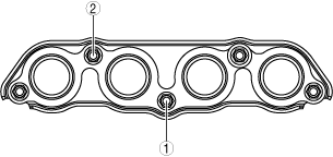
1. Temporarily tighten the exhaust manifold installation nuts (1) and (2) shown in the figure by hand.
ac5uuw00002679
|
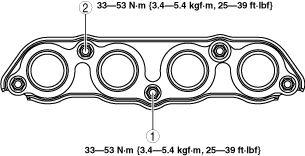
2. Tighten the exhaust manifold installation nuts (1) and (2) shown in the figure.
am3zzw00032167
|
3. Temporarily tighten the exhaust manifold installation nuts (3) to (5) shown in the figure by hand.
ac5wzw00002715
|
4. Tighten the exhaust manifold installation nuts (3) to (5) shown in the figure.
5. Tighten the exhaust manifold installation nuts (1) and (2) shown in the figure.
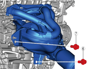
6. Temporarily tighten the bolts (6) and (7) shown in the figure.
ac5wzw00010633
|
7. Tighten the bolt (6) shown in the figure.
8. Tighten the bolt (7) shown in the figure.
9. Install the front crossmember. (See FRONT CROSSMEMBER REMOVAL/INSTALLATION [(E)].)
Exhaust Manifold Insulator Installation Note
1. Temporarily tighten the exhaust manifold insulator.
2. Tighten the exhaust manifold insulator in the order shown in the figure.
ac5wzw00010634
|
3. Install the insulators shown in the figure.
am3zzw00031802
|
4. Install the purge solenoid valve component.
ac5wzw00010695
|
5. Install the wiring harness clip shown in the figure.
ac5wzw00010682
|
6. Install the bolts shown in the figure. (See PURGE SOLENOID VALVE REMOVAL/INSTALLATION [SKYACTIV-G (WITH CYLINDER DEACTIVATION (E))].)
ac5wzw00010681
|
7. Install the plug hole plate. (See PLUG HOLE PLATE REMOVAL/INSTALLATION [SKYACTIV-G (WITH CYLINDER DEACTIVATION (E))].)
AWD
1. Disconnect the negative battery terminal. (See NEGATIVE BATTERY TERMINAL DISCONNECTION/CONNECTION [(E)].)
2. Remove the floor under cover No.1 (RH). (With Mazda M Hybrid) (See FLOOR UNDER COVER REMOVAL/INSTALLATION.)
3. Remove in the order indicated in the table.
4. Remove the insulator. (See Exhaust system insulator removal/installation.)
5. Install in the reverse order of removal.
Step 1
ac30zw00002264
|
|
1
|
Main silencer
|
|
2
|
Tunnel cover
|
|
3
|
Brace bar
(See Brace Bar Installation Note.)
|
|
4
|
Tunnel member
|
|
5
|
Connector
|
|
6
|
TWC component
(See TWC component Removal Note.)
|
|
7
|
HO2S
|
|
8
|
Exhaust shutter valve connector
|
|
9
|
TWC
|
Step 2
ac30zw00002257
|
|
1
|
A/F sensor
|
|
2
|
Clip
|
|
3
|
Insulator
|
|
4
|
Exhaust manifold insulator
|
|
5
|
Exhaust manifold (WU-TWC)
|
|
6
|
Exhaust manifold gasket
|
Exhaust system insulator removal/installation
1. Remove the floor under cover No.1 (RH). (Without Mazda M Hybrid) (See FLOOR UNDER COVER REMOVAL/INSTALLATION.)
2. Remove the floor under cover No.2. (See FLOOR UNDER COVER REMOVAL/INSTALLATION.)
3. Remove the Mazda M hybrid battery. (With Mazda M Hybrid) (See Mazda M Hybrid BATTERY REMOVAL/INSTALLATION.)
4. Remove the propeller shaft. (See PROPELLER SHAFT REMOVAL/INSTALLATION [(E)].)
5. Remove in the order indicated in the table.
6. Install in the reverse order of removal.
ac30zw00002265
|
|
1
|
Insulator (rear)
|
|
2
|
Insulator (front)
|
|
3
|
Insulator (middle)
|
TWC component Removal Note
1. Remove the floor under cover No.1 (LH). (See FLOOR UNDER COVER REMOVAL/INSTALLATION.)
2. Remove the TWC component.
Exhaust Manifold Insulator Removal Note
1. Remove the plug hole plate. (See PLUG HOLE PLATE REMOVAL/INSTALLATION [SKYACTIV-G (WITH CYLINDER DEACTIVATION (E))].)
2. Remove the bolts shown in the figure. (See PURGE SOLENOID VALVE REMOVAL/INSTALLATION [SKYACTIV-G (WITH CYLINDER DEACTIVATION (E))].)
ac5wzw00010681
|
3. Disconnect the wiring harness clip shown in the figure.
ac5wzw00010682
|
4. Set the purge solenoid valve component aside so that it does not interfere with the servicing.
ac5wzw00010695
|
5. Remove the insulators shown in the figure.
am3zzw00031802
|
6. Remove the exhaust manifold insulator.
Exhaust Manifold Removal Note
1. Remove the front crossmember. (See FRONT CROSSMEMBER REMOVAL/INSTALLATION [(E)].)
2. Remove the exhaust manifold.
Exhaust Manifold Installation Note
1. Temporarily tighten the exhaust manifold installation nuts (1) and (2) shown in the figure by hand.
ac5uuw00002679
|
2. Tighten the exhaust manifold installation nuts (1) and (2) shown in the figure.
am3zzw00032167
|
3. Temporarily tighten the exhaust manifold installation nuts (3) to (5) shown in the figure by hand.
ac5wzw00002715
|
4. Tighten the exhaust manifold installation nuts (3) to (5) shown in the figure.
5. Tighten the exhaust manifold installation nuts (1) and (2) shown in the figure.
6. Temporarily tighten the bolts (6) and (7) shown in the figure.
ac5wzw00010633
|
7. Tighten the bolt (6) shown in the figure.
8. Tighten the bolt (7) shown in the figure.
9. Install the front crossmember. (See FRONT CROSSMEMBER REMOVAL/INSTALLATION [(E)].)
Exhaust Manifold Insulator Installation Note
1. Temporarily tighten the exhaust manifold insulator.
2. Tighten the exhaust manifold insulator in the order shown in the figure.
ac5wzw00010634
|
3. Install the insulators shown in the figure.
am3zzw00031802
|
4. Install the purge solenoid valve component.
ac5wzw00010695
|
5. Install the wiring harness clip shown in the figure.
ac5wzw00010682
|
6. Install the bolts shown in the figure. (See PURGE SOLENOID VALVE REMOVAL/INSTALLATION [SKYACTIV-G (WITH CYLINDER DEACTIVATION (E))].)
ac5wzw00010681
|
7. Install the plug hole plate. (See PLUG HOLE PLATE REMOVAL/INSTALLATION [SKYACTIV-G (WITH CYLINDER DEACTIVATION (E))].)
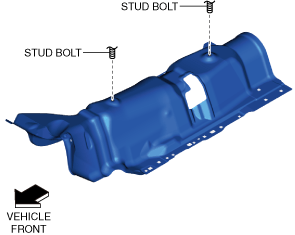
Insulator (middle) Installation Note
1. Align the stud bolts shown in the figure with the insulator (middle) and install.
2WD
ac30zw00002259
|
AWD
ac30zw00002266
|
2. Tighten the nuts to the specified torque.
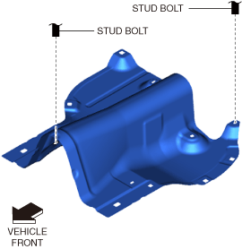
Insulator (front) Installation Note
1. Align the stud bolts shown in the figure with the insulator (front) and install.
am3zzw00021241
|
2. Install the fasteners.
3. Tighten the nuts to the specified torque.
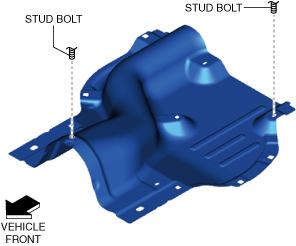
Insulator (Rear) Installation Note
1. Align the stud bolt shown in the figure with the insulator (rear) and install.
ac30zw00002260
|
2. Tighten the nuts to the specified torque.
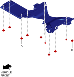
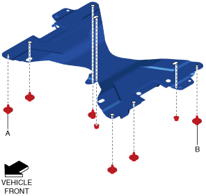
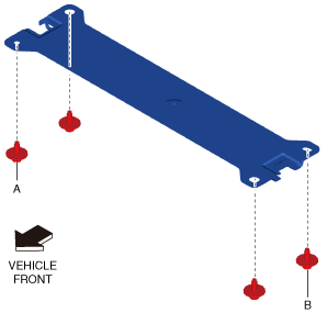
Tunnel Member Installation Note
1. Tighten bolt A shown in the figure to the specified torque.
With Mazda M Hybrid
ac30zw00004652
|
Without Mazda M Hybrid
ac30zw00004653
|
2. Tighten bolt B shown in the figure to the specified torque.
3. Tighten the remaining bolts and nuts to the specified torque.
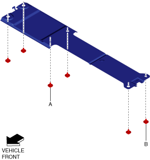
Brace Bar Installation Note
1. Tighten bolt A shown in the figure to the specified torque.
With Mazda M Hybrid
ac30zw00004654
|
Without Mazda M Hybrid
ac30zw00004655
|
2. Tighten bolt B shown in the figure to the specified torque.
3. Tighten the remaining bolts to the specified torque.
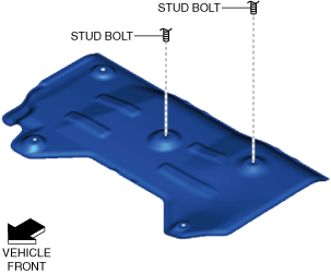
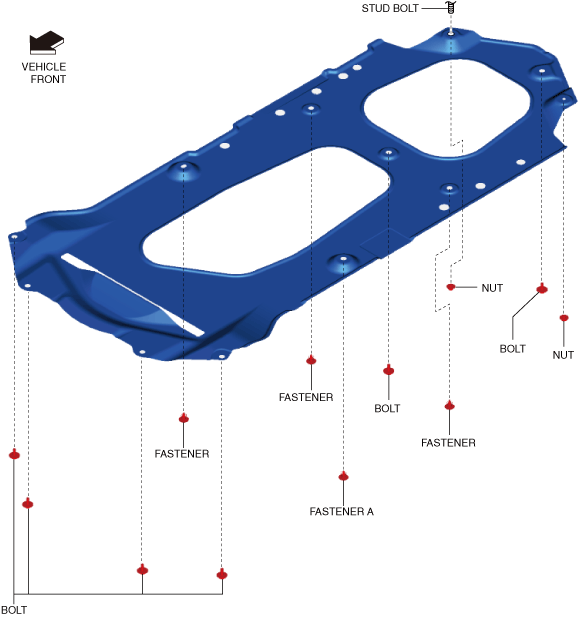
Tunnel Cover Installation Note
1. Align the stud bolt shown in the figure with the tunnel cover and install.
ac30zw00002263
|
2. Install fastener A shown in the figure.
3. Install the remaining fasteners.
4. Tighten the bolts shown in the figure to the specified torque.
5. Tighten the nuts shown in the figure to the specified torque.