Diagnostic procedure
|
STEP
|
INSPECTION
|
ACTION
|
|
|---|---|---|---|
|
1
|
VERIFY FREEZE FRAME DATA AND DIAGNOSTIC MONITORING TEST RESULTS HAS BEEN RECORDED
• Has FREEZE FRAME DATA been recorded?
|
Yes
|
Go to the next step.
|
|
No
|
Record the FREEZE FRAME on the repair order, then go to the next step.
|
||
|
2
|
VERIFY RELATED REPAIR INFORMATION AVAILABILITY
• Verify related Service Information availability.
• Is any related Service Information available?
|
Yes
|
Perform repair or diagnosis according to the available Service information.
If the vehicle is not repaired, go to the next step.
|
|
No
|
Go to the next step.
|
||
|
3
|
CLASSIFY HIGH INPUT OR LOW INPUT
• Connect the WDS or equivalent to DLC-2.
• Access CPP/PNP PID.
• Verify CPP/PNP PID when gear is neutral position.
• Is CPP/PNP PID always off?
|
Yes
|
Go to the next step.
|
|
No
|
Go to Step 10.
|
||
|
4
|
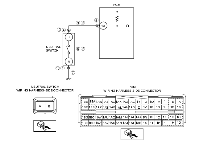
INSPECT NEUTRAL SWITCH CONNECTOR FOR POOR CONNECTION
• Turn the ignition switch off.
• Disconnect neutral switch connector.
• Inspect for poor connection (such as damaged/pulled-out pins, corrosion).
• Is there any malfunction?
|
Yes
|
Repair or replace the terminal, then go to Step 14.
|
|
No
|
Go to the next step.
|
||
|
5
|
CLASSIFY NEUTRAL SWITCH OR CIRCUIT
• Connect the WDS or equivalent to the DLC-2.
• Access CPP/PNP PID.
• Connect a jumper wire between neutral switch terminal A and B.
• Is CPP/PNP PID on?
|
Yes
|
Go to the next step.
|
|
No
|
Go to Step 7.
|
||
|
6
|
INSPECT NEUTRAL SWITCH
• Inspect the neutral switch.
• Is the neutral switch normal?
|
Yes
|
Go to Step 14.
|
|
No
|
Replace the neutral switch, then go to Step 14.
|
||
|
7
|
INSPECT NEUTRAL SWITCH GROUND CIRCUIT FOR OPEN CIRCUIT
• Inspect for continuity between neutral switch terminal A and ground.
• Is there continuity?
|
Yes
|
Go to the next step.
|
|
No
|
Repair or replace the neutral switch ground circuit for an open circuit, then Go to Step 14.
|
||
|
8
|
INSPECT PCM CONNECTOR FOR POOR CONNECTION
• Turn the ignition switch off.
• Disconnect the PCM connector.
• Inspect for poor connection (such as damaged/pulled-out pins, corrosion).
• Is there any malfunction?
|
Yes
|
Repair or replace the terminal, then go to Step 14.
|
|
No
|
Go to the next step.
|
||
|
9
|
INSPECT NEUTRAL SWITCH SIGNAL CIRCUIT FOR OPEN CIRCUIT
• Inspect for continuity between neutral switch terminal B and PCM terminal 1X.
• Is there continuity?
|
Yes
|
Repair or replace the wiring harness for an open circuit, then go to Step 14.
|
|
No
|
Go to Step 14.
|
||
|
10
|
INSPECT NEUTRAL SWITCH CONNECTOR FOR POOR CONNECTION
• Turn the ignition switch off.
• Disconnect the neutral switch connector.
• Inspect for poor connection (such as damaged/pulled-out pins, corrosion).
• Is there any malfunction?
|
Yes
|
Repair or replace the terminal, then go to Step 14.
|
|
No
|
Go to the next step.
|
||
|
11
|
CLASSIFY NEUTRAL SWITCH OR CIRCUIT
• Connect the WDS or equivalent to DLC-2.
• Access CPP/PNP PID.
• Verify that CPP/PNP PID changes from ON to OFF when the neutral switch connector disconnected.
• Does CPP/PNP PID change from ON to OFF?
|
Yes
|
Go to the next step.
|
|
No
|
Go to Step 13.
|
||
|
12
|
INSPECT NEUTRAL SWITCH
• Inspect the neutral switch.
• Is the neutral switch normal?
|
Yes
|
Go to Step 14.
|
|
No
|
Replace the neutral switch, then go to Step 14.
|
||
|
13
|
INSPECT NEUTRAL SWITCH SIGNAL CIRCUIT FOR SHORT TO GROUND
• Inspect for continuity between neutral switch terminal B and ground.
• Is there continuity?
|
Yes
|
Repair or replace the wiring harness for short to ground, then go to Step 14.
|
|
No
|
Go to the next step.
|
||
|
14
|
VERIFY TROUBLESHOOTING OF DTC P0850 COMPLETED
• Make sure to reconnect all disconnected connectors.
• Start the engine.
• Clear the DTC from the PCM memory using the WDS or equivalent.
• Drive the vehicle above 30 km/h {19 mph} and stop vehicle.
• Depress and release the clutch pedal more than 10 times during drive cycle.
• Is the PENDING CODE for this DTC present?
|
Yes
|
Replace the PCM, then go to the next step.
|
|
No
|
Go to the next step.
|
||
|
15
|
VERIFY AFTER REPAIR PROCEDURE
• Perform the "AFTER REPAIR PROCEDURE".
• Are any DTC present?
|
Yes
|
Go to the applicable DTC troubleshooting.
(See DTC TABLE [L8, LF, L3].)
|
|
No
|
Troubleshooting completed.
|
||