1. Disconnect the negative battery cable.
2. Remove the tire (RH).
3. Remove the splash shield (RH).
4. Remove the ignition coils. (See IGNITION COIL REMOVAL/INSTALLATION [L8, LF, L3, L3 Turbo])
5. Disconnect the oil control valve (OCV) connector.
6. Remove the ventilation hose.
7. Remove the cylinder head cover.
8. Remove the drive belt. (See DRIVE BELT REPLACEMENT [L8, LF, L3].)
9. Remove the joint shaft from the front drive shaft (RH). (See FRONT DRIVE SHAFT REMOVAL/INSTALLATION [L8, LF, L3, MZR-CD (RF Turbo)].)
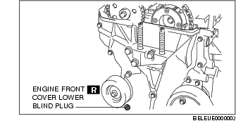
10. Remove the engine front cover lower blind plug.
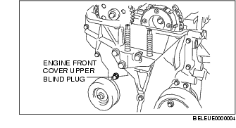
11. Remove the engine front cover upper blind plug.
12. Remove the cylinder block lower blind plug.
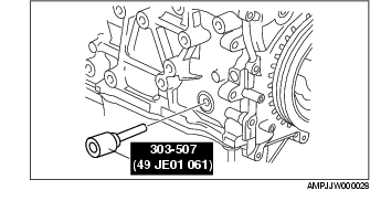
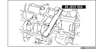
13. Install the SST as shown.
14. Turn the crankshaft clockwise the crankshaft is in the No.1 cylinder TDC position.
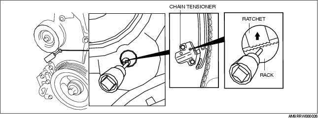
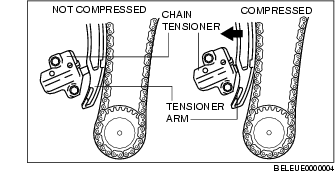
15. Loosen the timing chain using the following procedure.
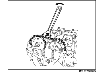

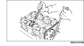
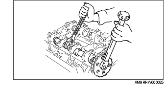
16. Hold the exhaust camshaft using a suitable wrench on the cast hexagon as shown.
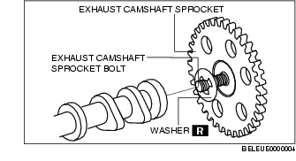
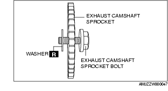
17. Remove the exhaust camshaft sprocket bolt, exhaust camshaft sprocket, and washer as a single unit.
18. Remove the OCV. (With variable valve timing mechanism.)(See OIL CONTROL VALVE (OCV) REMOVAL/INSTALLATION [LF, L3].)
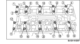
19. Loosen the camshaft cap bolts in several passes in the order shown.
20. Remove the camshaft.
21. Remove the tappet.
22. Select proper adjustment shim.
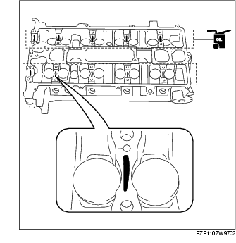
New adjustment shim23. Apply the gear oil (SAE No. 90 or equivalent) to each journal of the cylinder head as shown in the figure.
24. Install the camshaft with No.1 cylinder aligned with the TDC position.
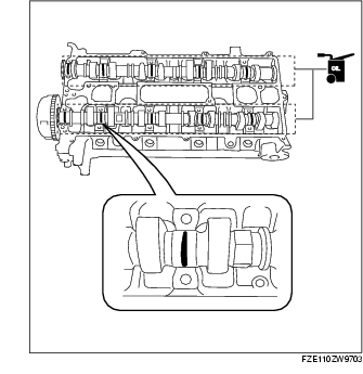
25. Apply the gera oil (SAE No. 90 or equivalent) to each journal of the camshaft as shown in the figure.
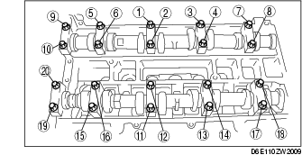
26. Tighten the camshaft cap bolt with the following two steps.
27. Install the OCV. (With variable valve timing mechanism.)(See OIL CONTROL VALVE (OCV) REMOVAL/INSTALLATION [LF, L3].)
28. Install the exhaust camshaft sprocket bolt, exhaust camshaft sprocket, and a new washer as a single unit.
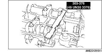
29. Install the SST to the camshaft as shown.
Europe
Except Europe
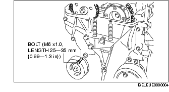
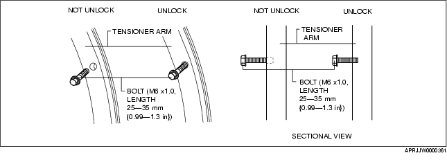
30. Remove the M6 X 1.0 bolt (length 25mm-35mm {0.99-1.37in}) from the engine front cover to apply tension to the timing chain.
31. Turn the crankshaft clockwise until the crankshaft is in the No.1 cylinder TDC position.
32. Hold the exhaust camshaft using a suitable wrench on the cast hexagon as shown.
33. Tighten the exhaust camshaft sprocket bolt.
Tightening torque34. Remove the SST from the camshaft.
35. Remove the SST from the block lower blind plug.
36. Rotate the crankshaft clockwise two turns until the TDC position.
37. Apply silicone sealant to the engine front cover upper blind plug.
38. Install the engine front cover upper blind plug.
Tightening torque
39. Install the cylinder block lower blind plug.
Tightening torque:
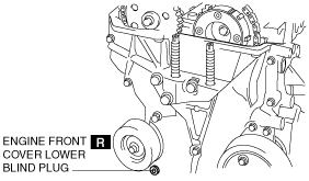
40. Install the new engine front cover lower blind plug.
Tightening torque:
41. Connect the front drive shaft (RH) and the joint shaft. (See FRONT DRIVE SHAFT REMOVAL/INSTALLATION [L8, LF, L3, MZR-CD (RF Turbo)].)
42. Install the drive belt. (See DRIVE BELT REPLACEMENT [L8, LF, L3].)
43. Install the cylinder head cover. (See Cylinder Head Cover Installation Note.)
44. Install the ventilation hose.
45. Connect the oil control valve (OCV) connector.
46. Install the ignition coils. (See IGNITION COIL REMOVAL/INSTALLATION [L8, LF, L3, L3 Turbo])
47. Install the splash shield (RH).
48. Install the tire (RH). (SeePRECAUTION (SUSPENSION).)