 |
am6zzw00007471
TIMING CHAIN REMOVAL/INSTALLATION [L8, LF, L3]
id0110a1801000
1. Disconnect the negative battery cable. (See BATTERY REMOVAL/INSTALLATION [L8, LF, L3, L3 Turbo].)
2. Remove the ignition coils. (See IGNITION COIL REMOVAL/INSTALLATION [L8, LF, L3, L3 Turbo])
3. Remove the tire (RH). (See PRECAUTION (SUSPENSION).)
4. Remove the under cover.
5. Loosen the water pump pulley bolt and removal the drive belt. (See DRIVE BELT REPLACEMENT [L8, LF, L3].)
6. Remove the CKP sensor. (See CRANKSHAFT POSITION (CKP) SENSOR REMOVAL/INSTALLATION [L8, LF, L3].)
7. Drain the engine oil. (See ENGINE OIL REPLACEMENT [L8, LF, L3, L3 Turbo].)
8. Remove the P/S oil pump with the oil hose still connected and position the P/S oil pump so that it is out of the way. (See POWER STEERING OIL PUMP REMOVAL/INSTALLATION [L8, LF, L3, L3 Turbo].)
9. Remove the front drive shaft (RH) from the joint shaft. (See JOINT SHAFT REMOVAL/INSTALLATION [L8, LF, L3, MZR-CD (RF Turbo)].)
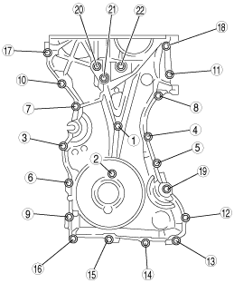
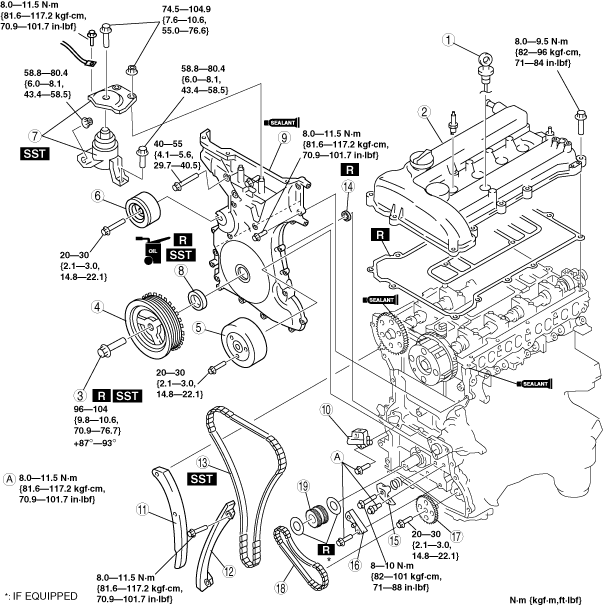
10. Remove in the order indicated in the table.
11. Install in the reverse order of removal.
12. Start the engine and:
13. Perform a road test.
am6zzw00007471
|
|
1
|
Dipstick
|
|
2
|
Cylinder head cover
|
|
3
|
Crankshaft pulley lock bolt
|
|
4
|
Crankshaft pulley
|
|
5
|
Water pump pulley
|
|
6
|
Drive belt idler pulley
|
|
7
|
No.3 engine mount rubber and No.3 engine joint bracket
|
|
8
|
Front oil seal
(See Front Oil Seal Removal Note.)
|
|
9
|
Engine front cover
|
|
10
|
Chain tensioner
(See Chain Tensioner Removal Note.)
|
|
11
|
Tensioner arm
|
|
12
|
Chain guide
|
|
13
|
Timing chain
|
|
14
|
Seal (L3)
|
|
15
|
Oil pump chain tensioner
|
|
16
|
Oil pump chain guide
|
|
17
|
Oil pump sprocket
|
|
18
|
Oil pump chain
|
|
19
|
Crankshaft sprocket
|
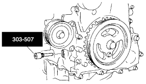
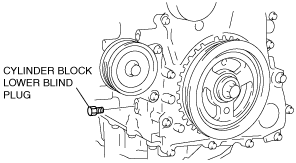
Crankshaft Pulley Lock Bolt Removal Note
1. Remove the cylinder block lower blind plug.
2. Install the SST.
am6zzw00007472
|
3. Turn the crankshaft clockwise until the crankshaft is in the No.1 cylinder TDC position (until the balance weight is attached to the SST).
4. Hold the crankshaft pulley by using the SSTs.
am6zzw00007473
|
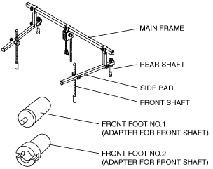
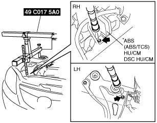
No.3 Engine Mount Rubber and No.3 Engine Joint Bracket Removal Note
1. Remove the air cleaner. (See INTAKE-AIR SYSTEM REMOVAL/INSTALLATION [L8, LF, L3].)
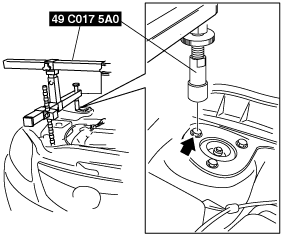
2. Install the SST using the following procedure.
am6zzw00007474
|
am6zzw00007475
|
am6zzw00007476
|
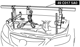
3. Support the engine using the SST.
am6zzw00007477
|
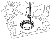
Front Oil Seal Removal Note
1. Remove the oil seal using a screwdriver as shown.
am6zzw00007478
|
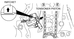
Chain Tensioner Removal Note
1. Using a thin screwdriver, hold the chain tensioner ratchet lock mechanism away from the ratchet stem.
2. Slowly compress the tensioner piston.
3. Hold the tensioner piston using a 1.5 mm {0.059 in} wire or paper clip.
am6zzw00007902
|
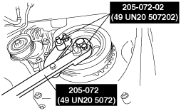
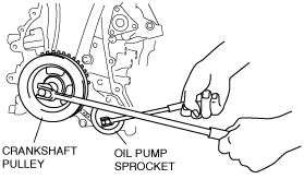
Oil Pump Sprocket Removal Note
1. Temporarily install the crankshaft pulley and crankshaft pulley lock bolt to the crankshaft, and lock the oil pump against rotation as shown in figure.
amxuuw00000712
|
2. Remove the oil pump sprocket, and then remove the crankshaft pulley and crankshaft pulley lock bolt.
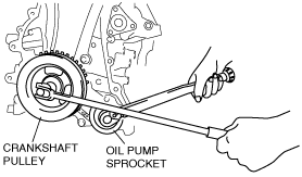
Oil Pump Sprocket Installation Note
1. Temporarily install the crankshaft pulley and crankshaft pulley lock bolt to the crankshaft, and lock the oil pump against rotation as shown in figure.
amxzzw00002401
|
2. Install the oil pump sprocket, and then remove the crankshaft pulley and crankshaft pulley lock bolt.
Timing Chain Installation Note
1. Install the SST to the camshaft as shown.
Europe
am6zzw00007903
|
Except Europe
am6zzw00007904
|
2. Install the timing chain.
3. Remove the retaining wire or paper clip from the auto tensioner to apply tension to the timing chain.
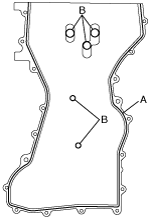
Engine Front Cover Installation Note
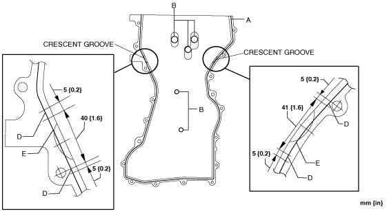
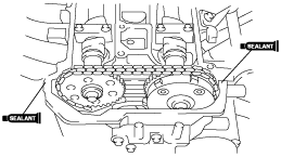
1. Apply silicone sealant to the engine front cover as shown.
Without crescent grooves at joint sections of cylinder head and cylinder block
am6zzw00007482
|
With crescent grooves at joint sections of cylinder head and cylinder block
aatjjw00004242
|
2. Install the engine front cover bolts in the order as shown.
am6zzw00007483
|
|
Bolt No. |
Tightening torque |
|---|---|
|
1—18
|
8.0—11.5 N·m {81.6—117.2 kgf·cm,70.9—101.7 in·lbf}
|
|
19—22
|
40—55 N·m {4.1—5.6 kgf·m, 29.7—40.5 ft·lbf}
|
Front Oil Seal Installation Note
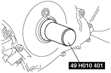
1. Apply clean engine oil to the oil seal.
2. Push the oil seal slightly in by hand.
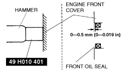
3. Compress the oil seal using the SST and a hammer.
am6zzw00007484
|
am6zzw00007485
|
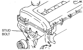
No.3 Engine Mount Rubber and No.3 Engine Joint Bracket Installation Note
1. Tighten the stud bolt of the No.3 engine mount bracket.
am6zzw00007486
|
2. Install the No.3 engine mount rubber hand-tighten.
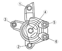
3. Tighten the No.3 engine joint bracket is attached and bolts, nuts in the order as shown.
am6zzw00007487
|
Crankshaft Pulley Lock Bolt Installation Note
1. Install the SST to the camshaft as shown.
Europe
am6zzw00007903
|
Except Europe
am6zzw00007904
|
2. Verify that cylinder No.1 is at TDC of the compression stroke. (Position crank weight contacts SST.)
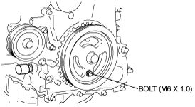
3. To position the crankshaft pulley, temporarily tighten it and, using a suitable bolt (M6 X 1.0 length 25—35 mm {0.99—1.37 in}), fix the crankshaft pulley to the engine front cover.
am6zzw00007905
|
4. Install the SSTs to the crankshaft pulley, lock the crankshaft against rotation, and tighten the crankshaft pulley lock bolt using the following two steps.
am6zzw00007473
|
5. Tighten the crankshaft pulley lock bolt using the following two steps.
6. Remove the M6 x 1.0 bolt.
7. Remove the SST from the camshaft.
8. Remove the SST from the cylinder block lower blind plug.
9. Rotate the crankshaft clockwise two turns until the TDC position.
10. Install the cylinder block lower blind plug.
am6zzw00007906
|
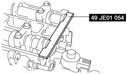
Cylinder Head Cover Installation Note
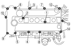
1. Apply silicone sealant to the mating faces as shown.
am6zzw00007490
|
2. Install the cylinder head cover with a new gasket.
3. Tighten the bolts in the order shown.
am6zzw00007491
|