 |
am6zzw00013024
VARIABLE VALVE TIMING ACTUATOR REMOVAL/INSTALLATION [L3 Turbo]
id0110b3803700
1. Disconnect the negative battery cable. (See BATTERY REMOVAL/INSTALLATION [L8, LF, L3, L3 Turbo].)
2. Remove the front tire (RH).
3. Remove the under cover.
4. Remove the splash shield (RH).
5. Remove the charge air cooler. (See INTAKE-AIR SYSTEM REMOVAL/INSTALLATION [L3 Turbo].)
6. Remove the high pressure fuel pump. (See HIGH PRESSURE FUEL PUMP REMOVAL/INSTALLATION [L3 Turbo].)
7. Remove the ignition coils. (See IGNITION COIL REMOVAL/INSTALLATION [L8, LF, L3, L3 Turbo].)
8. Disconnect the OCV connector.
9. Disconnect the CMP sensor connector.
10. Disconnect the P/S oil pump connector.
11. Remove the ventilation hose.
12. Remove the cylinder head cover. (See TIMING CHAIN REMOVAL/INSTALLATION [L3 Turbo].)
13. Remove the drive belt. (See DRIVE BELT REPLACEMENT [L3 Turbo].)
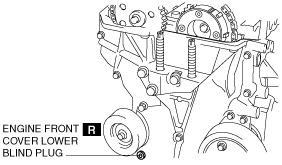
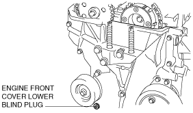
14. Remove the engine front cover lower blind plug.
am6zzw00013024
|
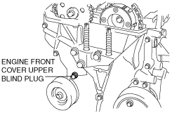
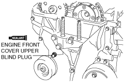
15. Remove the engine front cover upper blind plug.
am6zzw00013021
|
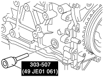
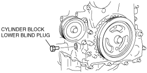
16. Remove the cylinder block lower blind plug, and install the SST.
am6zzw00007925
|
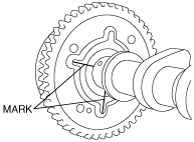
17. Rotate the crankshaft clockwise so that the No.1 cylinder is at TDC of the compression stroke. (The position counterweight contacts the SST.)
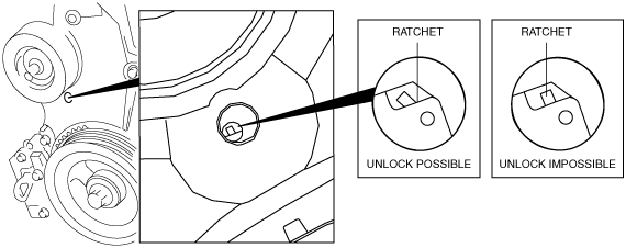
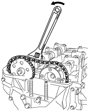
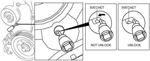
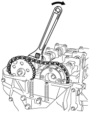
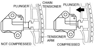
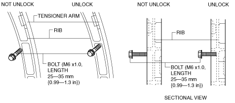
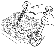
18. Loosen the timing chain using the following procedure.
Ratchet unlock position
beluce00000013
|
beleue00000041
|
am6zzw00007926
|
beltze00000124
|
am6zzw00007927
|
acxaaw00001397
|
am6zzw00007928
|
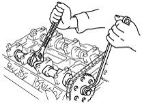
19. Fix the exhaust camshaft using a wrench on the cast hexagon, and loosen the camshaft sprocket bolt.
am6zzw00007929
|
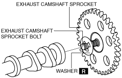
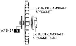
20. Remove the exhaust camshaft sprocket bolt, exhaust camshaft sprocket, and washer as a single unit.
beleue00000044
|
21. Remove the OCV. (See OIL CONTROL VALVE (OCV) REMOVAL/INSTALLATION [L3 Turbo].)
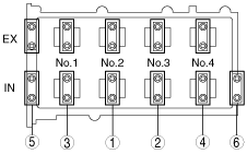
22. Loosen the camshaft cap bolts in two or three passes in the order shown in the figure and remove the camshaft cap.
am6zzw00004778
|
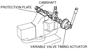
23. Remove the variable valve timing actuator and the camshaft on the intake air side as a single unit.
24. Remove the variable valve timing actuator.
am6zzw00004779
|
am6zzw00007931
|
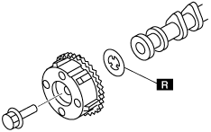
25. Install a new washer.
am6zzw00004780
|
26. Install the variable valve timing actuator.
27. Verify that the No.1 cylinder is at TDC of the compression stroke. (The position counterweight contacts the SST.)
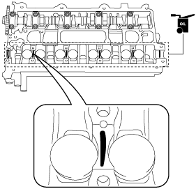
28. Apply the gear oil (SAE No. 90 or equivalent) to each journal of the cylinder head as shown in the figure.
am6zzw00004788
|
29. With No.1 cylinder cam aligned at TDC of the compression stroke, install the variable valve timing actuator and the camshaft on the intake air side as a single unit.
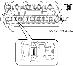
30. Apply the gear oil (SAE No. 90 or equivalent) to each journal of the camshaft as shown in the figure. However, do not apply it to the end journal of the intake camshaft.
acxaaw00001604
|
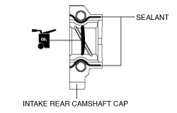
31. Carefully apply sealant agent (Loctite 518 or 962) to the area indicated in the figure so that it does not leak into the sliding part then, apply the gear oil (SAE No. 90 or equivalent) to the journal.
beltze00000119
|
32. Install the camshaft caps and temporarily tighten the camshaft cap bolts evenly in two or three passes, and then tighten the camshaft cap bolts in two passes, using the following two steps and in the order shown in the figure.
am6zzw00004784
|
33. Install the OCV. (See OIL CONTROL VALVE (OCV) REMOVAL/INSTALLATION [L3 Turbo].)
34. Install the timing chain, exhaust camshaft sprocket bolt, exhaust camshaft sprocket, and a new washer as a single unit.
acxuuw00002958
|
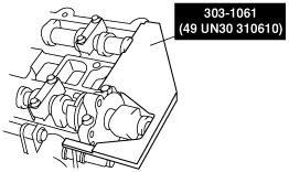
35. Install the SST on the camshaft as shown in the figure.
am6zzw00004785
|
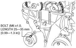
36. Remove the installation bolt for the engine front cover upper service hole (M6 X 1.0 length 25—35mm {0.99—1.37 in}), and apply tension to the timing chain.
37. Rotate the crankshaft clockwise and verify that the No.1 cylinder is at TDC of the compression stroke. (The position counterweight contacts the SST.)
38. Fix the exhaust camshaft using a wrench on the cast hexagon, and tighten the sprocket bolt.
azzjjn00000010
|
39. Remove the SST from the camshaft.
40. Remove the SST installed in the cylinder block lower blind plug hole.
41. Rotate the crankshaft clockwise two turns and inspect the valve timing.
42. Apply the silicone sealant and install the engine front cover upper blind plug.
am6zzw00004787
|
43. Install the cylinder block lower blind plug.
am6zzw00007930
|
44. Install a new engine front cover lower blind plug.
am6zzw00013020
|
45. Install the drive belt. (See DRIVE BELT REPLACEMENT [L3 Turbo].)
46. Install the cylinder head cover. (See TIMING CHAIN REMOVAL/INSTALLATION [L3 Turbo].)
47. Install the ventilation hose.
48. Connect the P/S oil pump connector.
49. Connect the CMP sensor connector.
50. Connect the OCV connector.
51. Install the ignition coils. (See IGNITION COIL REMOVAL/INSTALLATION [L8, LF, L3, L3 Turbo].)
52. Install the high pressure fuel pump. (See HIGH PRESSURE FUEL PUMP REMOVAL/INSTALLATION [L3 Turbo].)
53. Install the charge air cooler. (See INTAKE-AIR SYSTEM REMOVAL/INSTALLATION [L3 Turbo].)
54. Install the splash shield (RH).
55. Install the under cover.
56. Install the front tire (RH).
57. Connect the negative battery cable. (See BATTERY REMOVAL/INSTALLATION [L8, LF, L3, L3 Turbo].)