 |
am6zzw00008006
INTAKE-AIR SYSTEM REMOVAL/INSTALLATION [L3 Turbo]
id0113b5801900
1. Disconnect the negative battery cable. (See BATTERY REMOVAL/INSTALLATION [L8, LF, L3, L3 Turbo].)
2. Remove the charge air cooler cover.
3. Remove the battery and battery tray. (See BATTERY REMOVAL/INSTALLATION [L8, LF, L3, L3 Turbo].)
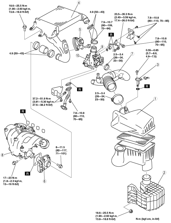
4. Remove in the order indicated in the table.
5. Install in the reverse order of removal.
6. Complete the “AFTER SERVICE PRECAUTION”. (See AFTER SERVICE PRECAUTION [L3 Turbo].)
7. Add the engine coolant to the cooling system filler neck and the coolant reserve tank to replace that during servicing. (Turbocharger not removed)
8. Refill the engine coolant. (Turbocharger removed)
9. Inspect the engine coolant level. (See ENGINE COOLANT LEVEL INSPECTION [L8, LF, L3, L3 Turbo].)
10. Inspect for engine coolant leakage. (See ENGINE COOLANT LEAKAGE INSPECTION [L8, LF, L3, L3 Turbo].)
11. Perform the following procedure.
am6zzw00008006
|
|
1
|
Air cleaner
|
|
2
|
Resonance chamber
|
|
3
|
MAF/IAT sensor
|
|
4
|
Charge air cooler
|
|
5
|
Air bypass valve
|
|
6
|
Throttle body
(See Throttle Body Removal Note.)
|
|
7
|
Air hose
(See Air Hose Removal Note.)
|
|
8
|
Intake manifold
(See Intake Manifold Removal Note.)
|
|
9
|
Wastegate control solenoid valve
|
|
10
|
Turbocharger
(See Turbocharger Removal Note.)
|
Resonance Chamber Removal Note
1. Remove the front mudguard (LH) before removing the resonance chamber.
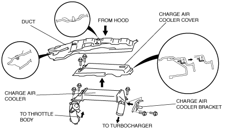
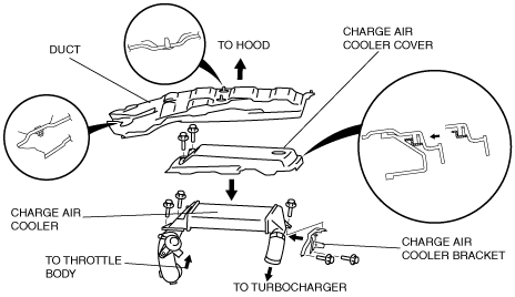
Charge Air Cooler Removal Note
1. Remove the duct.
am6zzw00008007
|
2. Remove the charge air cooler cover.
3. Remove the charge air cooler.
4. Remove the charge air cooler bracket.
Throttle Body Removal Note
Turbocharger not removed
1. Wrap a clean cloth around the cooling system cap and release the pressure by loosening the cap slowly.
2. Remove the water hose from the throttle body and plug the water hose quickly.
3. Remove the throttle body.
Turbocharger removed
1. Drain the engine coolant before disconnect the water hose. (See ENGINE COOLANT REPLACEMENT [L8, LF, L3, L3 Turbo].)
2. Remove the throttle body.
Air Hose Removal Note
1. Disconnect the EGR valve connector.
2. Remove the air hose.
Intake Manifold Removal Note
1. Remove the high pressure fuel pump bracket and the EGR pipe bracket.
2. Remove the fuel delivery pipe cover.
am6zzw00008008
|
3. Remove the oil level gauge pipe. (See OIL PAN REMOVAL/INSTALLATION [L3 Turbo].)
4. Remove the drive belt. (See DRIVE BELT REPLACEMENT [L3 Turbo].)
5. Set the power steering pump out of the way.
6. Remove the vacuum hose.
7. Remove the intake manifold.
Turbocharger Removal Note
1. Remove the TWC. (See EXHAUST SYSTEM REMOVAL/INSTALLATION [L3 Turbo].)
2. Disconnect the HO2S connector.
3. Remove the front pipe. (See EXHAUST SYSTEM REMOVAL/INSTALLATION [L3 Turbo].)
4. Remove the cowl and the insulator under the cowl. (See COWL GRILLE REMOVAL/INSTALLATION.)
5. Remove the insulator (Exhaust manifold upper side). (See EXHAUST SYSTEM REMOVAL/INSTALLATION [L3 Turbo].)
6. Set the generator out of the way. (See GENERATOR REMOVAL/INSTALLATION [L3 Turbo].)
7. Remove the insulator (Exhaust manifold lower side). (See EXHAUST SYSTEM REMOVAL/INSTALLATION [L3 Turbo].)
8. Disconnect the A/F sensor connector.
9. Remove the insulator (WU-TWC top side). (See EXHAUST SYSTEM REMOVAL/INSTALLATION [L3 Turbo].)
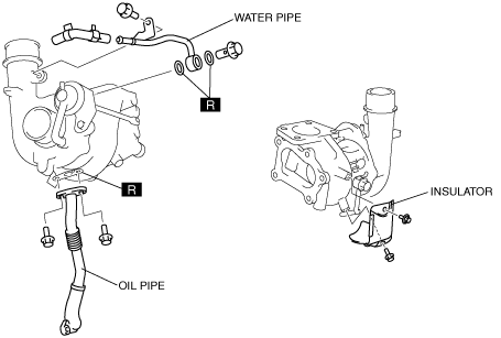
10. Remove the vacuum hose (Brake master back side).
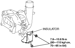
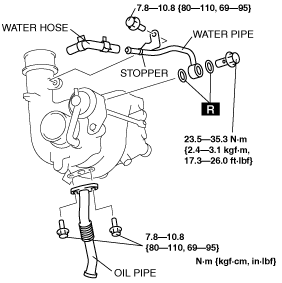
11. Remove the oil pipe, water pipe, and insulator.
am6zzw00008009
|
12. Remove the A/F sensor. (See EXHAUST SYSTEM REMOVAL/INSTALLATION [L3 Turbo].)
13. Remove the WU-TWC. (See EXHAUST SYSTEM REMOVAL/INSTALLATION [L3 Turbo].)
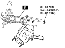
14. Remove the turbocharger.
am6zzw00008010
|
Turbocharger Installation Note
1. Install the turbocharger.
am6zzw00008010
|
2. Install the WU-TWC. (See EXHAUST SYSTEM REMOVAL/INSTALLATION [L3 Turbo].)
3. Install the A/F sensor. (See EXHAUST SYSTEM REMOVAL/INSTALLATION [L3 Turbo].)
4. Install the insulator.
am6uuw00001787
|
5. Install the oil pipe and water pipe, then insert the water hose until it reaches the stopper.
am6uuw00001788
|
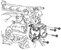
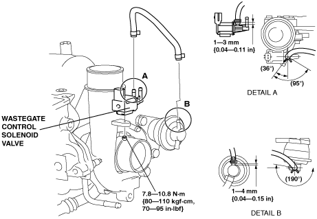
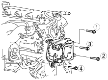
Wastegate Control Solenoid Valve Installation Note
1. Install the wastegate control solenoid valve.
am6zzw00008011
|
2. Install the hose as shown in the figure.
Intake Manifold Installation Note
1. Install the intake manifold.
2. Install the vacuum hose.
3. Install the drive belt.
4. Install the oil level gauge pipe. (See OIL PAN REMOVAL/INSTALLATION [L3 Turbo].)
5. Install the fuel delivery pipe cover in the order in the figure.
am6zzw00008012
|
6. Install the high pressure fuel pump bracket and the EGR pipe bracket.
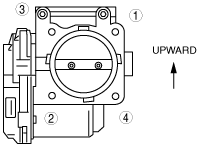
Throttle Body Installation Note
1. Tighten the throttle body installation bolts in the order shown in the figure.
am6zzw00008014
|
2. Remove the plug from the engine coolant hose and install the water hose to the throttle body quickly. (Turbocharger not removed)
3. Install the water hose to the throttle body. (Turbocharger removed)
Charge Air Cooler Installation Note
am6zzw00008013
|
1. Install the charge air cooler bracket.
2. Install the charge air cooler.
3. install the charge air cooler cover.
4. install the duct.
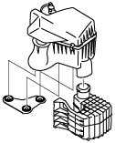
Air Cleaner Case Installation Note
am6zzw00008015
|
1. Verify that the rubber mounts are set in the air cleaner bracket (3 locations).
2. Install the projections on the frame side (2 locations).
3. Verify that the projections on the frame side are installed securely.
4. Install the projection on the engine side (remaining location).
5. Verify that the projection on the engine side installed securely.