1. Remove the negative battery cable.
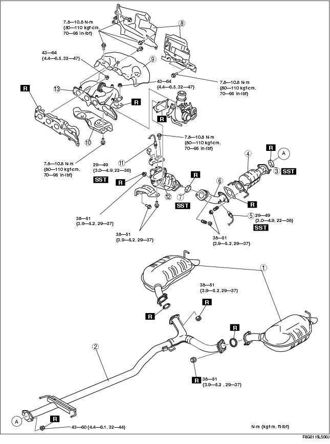
2. Remove in the order indicated in the table.
3. Install in the reverse order of removal.
.
|
1
|
Main silencer
|
|
2
|
Middle pipe
|
|
3
|
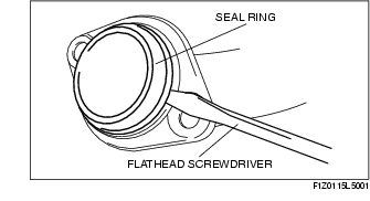
Seal ring (TWC side)
(See Seal Ring Removal Note.)
|
|
4
|
TWC
|
|
5
|
HO2S
|
|
6
|
Front pipe
(See Front Pipe Installation Note.)
|
|
7
|
Seal ring (WU-TWC side)
(See Seal Ring Removal Note.)
|
|
8
|
Insulator
(See Insulator Removal Note.)
|
|
9
|
Exhaust manifold insulator (Upper)
|
|
10
|
Exhaust manifold insulator (Lower)
|
|
11
|
A/F sensor
|
|
12
|
WU-TWC
(See WU-TWC Removal Note.)
(See WU-TWC Installation Note.)
|
|
13
|
Exhaust manifold
|
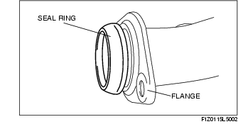
1. Remove the seal ring using a flathead screwdriver being careful not to damage the pipe.
1. Remove the insulator (WU-TWC top side). (A/F sensor)
2. Remove the battery and battery tray. (See BATTERY REMOVAL/INSTALLATION [L8, LF, L3, L3 Turbo].)
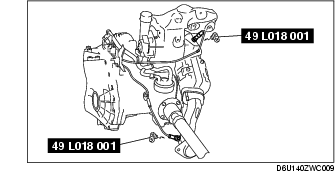
3. Remove the A/F sensor, HO2S using the SST before removing the exhaust manifold.
1. Remove the charge air cooler and the charge air cooler bracket. (See INTAKE AIR SYSTEM REMOVAL/INSTALLATION [L3 Turbo].)
2. Remove the cowl grille. (See COWL GRILLE REMOVAL/INSTALLATION.)
3. Remove the insulators.
1. Set the generator out of the way.
2. Disconnect the vacuum hose (Master cylinder side).
3. Remove the WU-TWC.
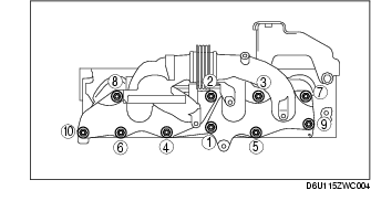
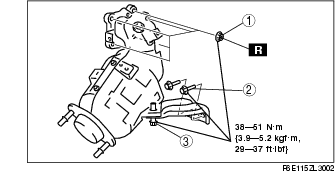
1. Tighten the exhaust manifold installation nuts in the order shown.
Tightening torque
1. Temporarily tighten No.1 shown in the figure.
2. Temporarily tighten No.2 shown in the figure.
3. Temporarily tighten No.3 shown in the figure.
4. Completely tighten No.1 shown in the figure.
Tightening torque5. Completely tighten No.2 shown in the figure.
Tightening torque6. Completely tighten No.3 shown in the figure.
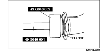
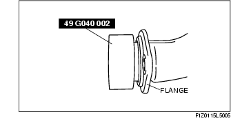
Tightening torque1. Temporarily install the seal ring to the pipe so that the seal ring is even with the flange.
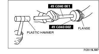
2. Install the SST to the seal ring so that the SST is even with the flange.
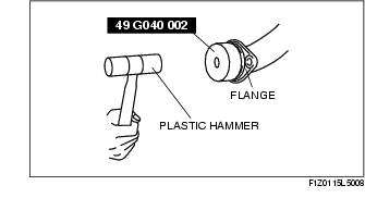
3. Press in the seal ring by tapping the SST using a plastic hammer until the seal ring contacts the flange.
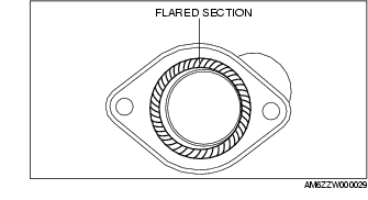
1. Spray carbon remover (TB6601 or equivalent) on the flared section of the exhaust pipe.
2. Remove the carbon adhering to the flared section shown in the figure using a nylon brush or sandpaper (No. 400 or equivalent).
1. Temporarily install the seal ring to the pipe so that the seal ring is even with the flange.
2. Install the SST to the seal ring so that the SST is even with the flange.
3. Press in the seal ring by tapping the SST using a plastic hammer until the seal ring contacts the flange.
1. Spray carbon remover (TB6601 or equivalent) on the flared section of the exhaust pipe.
2. Remove the carbon adhering to the flared section shown in the figure using a nylon brush or sandpaper (No. 400 or equivalent).
1. Set the middle pipe mount, and temporarily tighten to the catalytic converter.
2. Set the left and right main silencer mounts, and temporarily tighten to the middle pipe.
3. Completely tighten the installation nuts between the catalytic converter and middle pipe.
Tightening torque4. Completely tighten the installation nuts between main silencer and middle pipe in the order of left side, then right side.
Tightening torque