 |
am6zzw00004718
EXHAUST SYSTEM REMOVAL/INSTALLATION [MZR-CD (RF Turbo)]
id0115f1800200
|
STEP |
ACTION |
PAGE/CONDITION |
|---|---|---|
|
1
|
Replace the oxidation catalytic converter.
|
–
|
|
2
|
Turn the engine switch on.
|
–
|
|
3
|
Perform diesel particulate filter data reset procedure.
|
|
|
4
|
Start the engine.
|
Verify that the MIL does not illuminate.
|
|
5
|
Turn the engine switch off.
|
–
|
|
6
|
Turn the engine switch on (Engine off).
|
–
|
|
7
|
Perform KOEO self-test procedure.
|
|
|
8
|
Perform diesel particulate filter reset procedure.
|
–
|
|
9
|
Turn the engine switch off.
|
–
|
|
10
|
Wait for 20 s.
|
–
|
|
11
|
Start the engine.
|
–
|
|
12
|
Perform KOER self-test procedure.
|
Warm up until the exhaust gas temperature (EXHTEMP1, EXHTEMP2, EXHTEMP3 PID) is 100 °C {212 °F} or more.
|
|
13
|
Perform fuel injector injection amount correction procedure.
|
Engine coolant temperature 65—95 °C {149—203 °F}.
Intake air temperature 15—65 °C {59—149 °F}.
Fuel temperature 30—60 °C {86—140 °F}.
|
|
14
|
Perform diesel particulate filter assessment procedure.
|
Engine coolant temperature 60 °C {140 °F} or more.
|
|
15
|
Perform diesel particulate filter regeneration procedure.
|
Engine coolant temperature 70 °C {158 °F} or more.
|
|
16
|
Perform after repair procedure.
|
|
|
17
|
Turn the engine switch off.
|
–
|
1. Disconnect the negative battery cable.
2. Remove the engine cover.
3. Remove in the order indicated in the table.
4. Install in the reverse order of removal.
5. Start the engine and:
am6zzw00004718
|
|
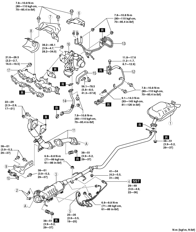
1
|
Main silencer
|
|
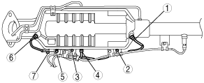
2
|
Exhaust gas pressure hose
|
|
3
|
Oxidation catalytic converter (built-in diesel particulate filter)
|
|
4
|
A/F sensor
|
|
5
|
Exhaust gas temperature sensor
|
|
6
|
Turbocharger insulator No.1
|
|
7
|
Turbocharger insulator No.2
|
|
8
|
Exhaust manifold insulator
|
|
9
|
Front pipe bracket No.1
|
|
10
|
Front pipe bracket No.2
|
|
11
|
Front pipe
|
|
12
|
Oil pipe (supply)
|
|
13
|
Water pipe
(See Water Pipe Removal Note)
|
|
14
|
Oil pipe (return)
|
|
15
|
Turbocharger bracket
|
|
16
|
Turbocharger
|
|
17
|
Exhaust manifold
|
Water Pipe Removal Note
1. Drain the engine coolant before removing the water pipe. (See ENGINE COOLANT REPLACEMENT [MZR-CD (RF Turbo)].)
Turbocharger Removal Note
1. Remove the battery. (See BATTERY REMOVAL/INSTALLATION [MZR-CD (RF Turbo)].)
2. Remove the fuel filter component with the hose still connected. Position the fuel filter component so that it is out of the way. (R.H.D.) (See FUEL FILTER COMPONENT REMOVAL/INSTALLATION [MZR-CD (RF Turbo)].)
Exhaust Manifold Removal Note
1. Remove the EGR cooler before removing the exhaust manifold. (See EGR COOLER REMOVAL/INSTALLATION [MZR-CD (RF Turbo)].)
Exhaust Manifold Installation Note
1. Tighten the exhaust manifold installation nuts in the order shown.
am6zzw00004719
|
2. Install the EGR cooler. (See EGR COOLER REMOVAL/INSTALLATION [MZR-CD (RF Turbo)].)
Water Pipe Installation Note
1. Tighten the water pipe installation nuts in the order shown.
am6zzw00004720
|
2. Refill the engine coolant after Installing the water pipe. (See ENGINE COOLANT REPLACEMENT [MZR-CD (RF Turbo)].)
Oil Pipe (Supply) Installation Note
1. Tighten the Oil pipe (supply) installation bolts in the order shown.
am6zzw00004721
|
Front Pipe Installation Note
1. Tighten the bolts A.
am6zzw00004722
|
2. Tighten the bolt B and nuts E.
3. Verify that brackets X, Y and Z are each properly installed.
4. Tighten the bolts C.
5. Tighten the bolts D.
Exhaust Gas Temperature Sensor Installation Note
1. Remove the burn protection agent from the installation hole of the exhaust gas temperature sensor.
am6zzw00004723
|
2. Apply the burn protection agent to the threads of the nuts and the exhaust gas temperature sensor, and tighten the sensor and nuts in the order shown in the figure.