AIR FUEL RATIO (A/F) SENSOR, HEATED OXYGEN SENSOR (HO2S) INSPECTION [L3 Turbo]
AIR FUEL RATIO (A/F) SENSOR, HEATED OXYGEN SENSOR (HO2S) INSPECTION [L3 Turbo]
id0140b6899800
-
Note
-
• Before performing the following inspection, make sure to follow the troubleshooting flowchart. (See FOREWORD [L3 Turbo].)
A/F Sensor Current Inspection
1. Warm up the engine to normal operating temperature.
2. Using the WDS or equivalent, monitor the following:
-
- Vehicle speed (PID: VSS)
-
- Engine speed (PID: RPM)
-
- A/F sensor current (PID: O2S11)
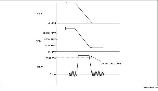
3. Drive the vehicle and decelerate the engine speed by releasing the accelerator pedal fully when the engine speed is 3,000 rpm or more.
4. Verify that the A/F sensor current (PID: O2S11) is 0.25 mA or more while decelerating as shown in the figure.
-
• If not within the specification, inspect the A/F sensor for an open or short circuit. (See A/F Sensor Circuit Open/short Inspection (Sensor).) Then if there is no malfunction in the wiring harness, replace the A/F sensor.
A/F Sensor Heater Resistance Inspection
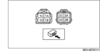
1. Disconnect the A/F sensor connector.
2. Measure the resistance between A/F sensor terminals 2B and 2D.
-
• If not within the specification, replace the A/F sensor. (See EXHAUST SYSTEM REMOVAL/INSTALLATION [L3 Turbo].)
A/F sensor heater resistance
-
1-10 ohms
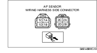
A/F Sensor Circuit Open/short Inspection (Sensor)
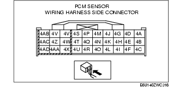
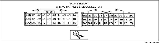
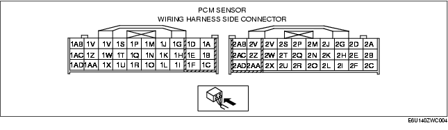
1. Disconnect the PCM connector.
2. Disconnect the A/F sensor connector.
3. Inspect the following wiring harnesses for an open or short circuit. (Continuity inspection)
Open circuit
• If there is no continuity in the following wiring harnesses, there is an open circuit. Repair or replace the wiring harness.
-
- A/F sensor terminal 1A and PCM terminal 2D
-
- A/F sensor terminal 1B and PCM terminal 2G
-
- A/F sensor terminal 1C and PCM terminal 2J
-
- A/F sensor terminal 2A and PCM terminal 2H
-
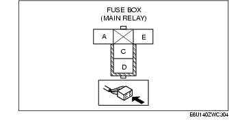
- A/F sensor terminal 2B and main relay terminal C
-
- A/F sensor terminal 2C and PCM terminal 2M
-
- A/F sensor terminal 2D and PCM terminal 4AD
Short circuit
• If there is continuity in the following wiring harnesses, there is a short circuit. Repair or replace the wiring harness.
-
- A/F sensor terminal 1A and body ground
-
- A/F sensor terminal 1A and power supply
-
- A/F sensor terminal 1B and body ground
-
- A/F sensor terminal 1B and power supply
-
- A/F sensor terminal 1C and body ground
-
- A/F sensor terminal 1C and power supply
-
- A/F sensor terminal 2A and power supply
-
- A/F sensor terminal 2B and body ground
-
- A/F sensor terminal 2C and body ground
-
- A/F sensor terminal 2C and power supply
-
- A/F sensor terminal 2D and body ground
-
- A/F sensor terminal 2D and power supply
HO2S Voltage Inspection
1. Warm up the engine to normal operating temperature.
2. Using the WDS or equivalent, monitor the following:
-
- Vehicle speed (PID: VSS)
-
- Engine speed (PID: RPM)
-
- HO2S voltage (PID: O2S12)
3. Drive the vehicle and decelerate the engine speed by releasing the accelerator pedal fully when the engine speed is 3,000 rpm or more.
4. Verify that the HO2S outputs a voltage of 0.6 V or more, one time or more, then verify that the HO2S voltage (PID: O2S12) is 0.3 V or less while decelerating as shown in the figure.
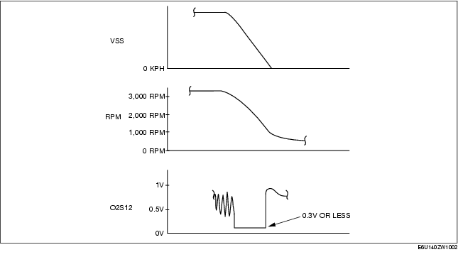
-
• If not within the specification, inspect the HO2S for an open or short circuit. (See HO2S Circuit Open/short Inspection (Sensor).) Then if there is no malfunction in the wiring harness, replace the HO2S.
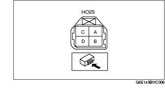
HO2S Circuit Open/short Inspection (Sensor)
1. Disconnect the PCM connector.
2. Disconnect the HO2S connector.
3. Inspect the following wiring harnesses for an open or short circuit. (Continuity inspection)
Open circuit
• If there is no continuity, there is an open circuit. Repair or replace the wiring harness.
-
- HO2S terminal A and PCM terminal 1Y
-
- HO2S terminal B and PCM terminal 2H
Short circuit
• If there is continuity, there is a short circuit. Repair or replace the wiring harness.
-
- HO2S terminal A and body ground
-
- HO2S terminal A and power supply
-
- HO2S terminal B and power supply
HO2S Heater Resistance Inspection
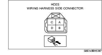
1. Disconnect the HO2S connector.
2. Measure the HO2S resistance between terminals C and D.
-
• If not within the specification, replace the HO2S.
HO2S heater resistance
-
2-50 ohms
HO2S Circuit Open/short Inspection (Heater)
1. Disconnect the PCM connector.
2. Disconnect the HO2S connector.
3. Inspect the following wiring harnesses for an open or short circuit. (Continuity inspection)
Open circuit
• If there is no continuity, there is an open circuit. Repair or replace the wiring harness.
-
- HO2S terminal C and ignition switch
-
- HO2S terminal D and PCM terminal 4Z
Short circuit
• If there is no continuity, there is a short circuit. Repair or replace the wiring harness.
Rear
-
- HO2S terminal C and body ground
-
- HO2S terminal D and power supply
-
- HO2S terminal D and body ground