|
STEP
|
INSPECTION
|
ACTION
|
|
1
|
VERIFY FREEZE FRAME DATA HAS BEEN RECORDED
• Has FREEZE FRAME PID DATA been recorded?
|
Yes
|
Go to next step.
|
|
No
|
Record FREEZE FRAME PID DATA on repair order, then go to next step.
|
|
2
|
VERIFY RELATED REPAIR INFORMATION AVAILABILITY
• Check for related Service Bulletins and/or on-line repair information availability.
• Is any related repair information available?
|
Yes
|
Perform repair or diagnosis according to available repair information.
• If vehicle is not repaired, go to next step.
|
|
No
|
Go to next step.
|
|
3
|
INSPECT TCM CONNECTOR FOR POOR CONNECTION
• Turn ignition key to OFF.
• Check for poor connection (damaged pulled-out terminals, corrosion, etc.).
• Are terminals okay?
|
Yes
|
Go to next step.
|
|
No
|
Repair terminals, then go to Step 12.
|
|
4
|
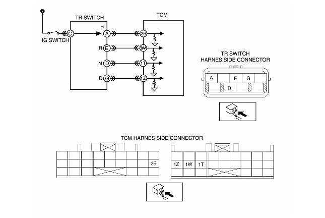
INSPECT TR SWITCH CIRCUIT
• Connect voltmeter to TCM.
• Inspect TCM terminal voltage.
-
- TCM terminal 2B
-
• P position: B+
-
• Other positions and all ranges: 0V
-
- TCM terminal 1W
-
• R position: B+
-
• Other position and all ranges: 0V
-
- TCM terminal 1T
-
• N position: B+
-
• Other position and all range: 0V
-
- TCM terminal 1Z
-
• D range: B+
-
• Other ranges and all positions: 0V
• Are any of following terminal voltage turned on for even a moment while shifting selector lever slowly from P position to D range?
|
Yes
|
Adjust TR switch, then go to Step 12.
|
|
No
|
Go to next step.
|
|
5
|
INSPECT TR SWITCH CONNECTOR FOR POOR CONNECTION
• Turn ignition key to OFF.
• Check for poor connection (damaged pulled-out terminals, corrosion, etc.).
• Are terminals okay?
|
Yes
|
Go to next step.
|
|
No
|
Repair terminals, then go to Step 12.
|
|
6
|
INSPECT TR SWITCH CIRCUIT
• Disconnect TR switch connector.
• Connect voltmeter to TCM.
• Turn ignition key to ON (engine OFF).
• Connect harness side connector power line and signal line using jumper wire
-
- P position: C and A
-
- R position: C and E
-
- N position: C and D
-
- D range: C and G
• Inspect if terminal voltage changes.
-
- 0V to B+
• Does terminal voltage change?
|
Yes
|
Go to next step.
|
|
No
|
Go to Step 9.
|
|
7
|
INSPECT TR SWITCH FOR OPEN CIRCUIT
• Turn ignition key to OFF.
• Inspect continuity between TR switch terminals (part side).
-
- P position: C and A
-
- R position: C and E
-
- N position: C and D
-
- D range: C and G
• Is there continuity between TR switch terminals (part side)?
|
Yes
|
Go to Step 12.
|
|
No
|
Replace TR switch, then go to Step 12.
|
|
8
|
INSPECT TR SWITCH POWER CIRCUIT FOR OPEN CIRCUIT
• Check voltage at TR switch terminal C (harness-side).
• Is there B+ at TR switch terminal C (harness-side)?
|
Yes
|
Go to next step.
|
|
No
|
Inspect main fuse.
• If okay, repair or replace wiring, then go to Step 12.
|
|
9
|
INSPECT PCM CONNECTOR FOR POOR CONNECTION
• Turn ignition key to OFF.
• Check for poor connection (damaged pulled-out terminals, corrosion, etc.).
• Are terminals okay?
|
Yes
|
Go to next step.
|
|
No
|
Repair terminals, then go to Step 12.
|
|
10
|
INSPECT TR SWITCH SIGNAL CIRCUIT FOR OPEN CIRCUIT
• Check continuity between TR switch terminals (harness-side) and TCM terminals (harness-side).
-
- P position: A and 2B
-
- R position: E and 1W
-
- N position: D and 1T
-
- D range: G and 1Z
• Is there continuity?
|
Yes
|
Go to next step.
|
|
No
|
Repair or replace harness, then go to Step 12.
|
|
11
|
INSPECT TR SWITCH CIRCUIT FOR SHORT TO GROUND
• Check continuity between TCM terminals (harness-side) and body ground.
-
- P position: 2B and body ground
-
- R position: 1W and body ground
-
- N position: 1T and body ground
-
- D range: 1Z and body ground
• Is there continuity?
|
Yes
|
Go to next step.
|
|
No
|
Repair or replace harness, then go to next step.
|
|
12
|
VERIFY TROUBLESHOOTING OF DTC P0706 COMPLETED
• Make sure to reconnect all disconnected connectors.
• Clear DTC from memory using WDS or equivalent.
• Drive vehicle in each range (P, R, N, and D) for 100 s or more.
• Is there pending code present?
|
Yes
|
Replace TCM, then go to next step.
|
|
No
|
Go to next step.
|
|
13
|
VERIFY AFTER REPAIR PROCEDURE
• Perform "After Repair Procedure".
• Is there any DTC present?
|
Yes
|
Go to applicable DTC inspection.
|
|
No
|
Troubleshooting completed.
|