Home

Mazdamanuals.com

 STEERING GEAR AND LINKAGE REMOVAL/INSTALLATION [L8, LF, L3 (2WD)]

STEERING GEAR AND LINKAGE REMOVAL/INSTALLATION [L8, LF, L3 (2WD)]


id0614008009a6

Caution
• Performing the following procedures without first removing the ABS wheel-speed sensor may possibly cause an open circuit in the harness if it is pulled by mistake. Before performing the following procedures, remove the ABS wheel-speed sensor (axle side) and fix it to an appropriate place where the sensor will not be pulled by mistake while servicing the vehicle.

1. Remove in the order indicated in the table.

2. Install in the reverse order of removal.

3. After installation, inspect the toe-in. (See FRONT WHEEL ALIGNMENT.)

.

1
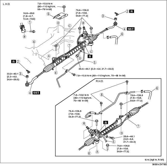
Bolt (intermediate shaft)
2
Cotter pin
3
Nuts (tie-rod end ball joint)
4
Tie-rod end ball joint
5
Pressure pipe
6
Return hose
7
Steering gear and linkage
8
Return pipe
9
Insulator (18 inch wheel)

Bolt (Intermediate Shaft) Removal Note

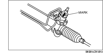
1. Mark the pinion shaft and gear housing for proper installation.

Tie-rod End Ball Joint Removal Note

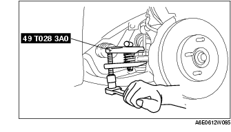
1. Remove the tie rod-nut.

2. Separate the tie-rod end from the steering knuckle using the SSTs.

Steering Gear and Linkage Removal Note

L.H.D.

Caution
• Excessively loosening the crossmember nuts may possibly cause the crossmember to fall off. The crossmember nuts must remain threaded on the studs when loosening.

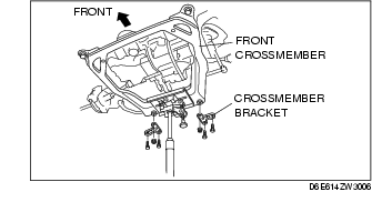
1. Support the crossmember using jack before removing the crossmember bracket.

2. Loosen the jack and lower the crossmember.

3. Remove the steering gear and linkage by pulling it from the left side.

R.H.D.

1. Remove the steering gear and linkage by pulling it from the right side.

Steering Gear and Linkage Installation Note

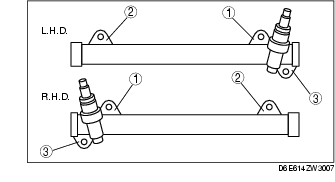
1. Loosely tighten bolts.

2. Tighten the mounting bracket bolts to the specified torque in the order shown.

Tightening torque
74.4-104.8 N·m {7.6-10.6 kgf·m, 55-77 ft·lbf}

3. Tighten the crossmember installation nuts. (L.H.D.)

Tightening torque
Nut: 119.6-154.8 N·m {12.2-15.7 kgf·m, 89-114 ft·lbf}
Bolt (silver): 93.1-131.3 N·m {9.5-13.3 kgf·m, 68.7-96.8 ft·lbf}
Bolt (green): 73.6-103.8 N·m {7.6-10.5 kgf·m, 54.3-76.5 ft·lbf}

Bolt (Intermediate Shaft) Installation Note

1. Align the marks and install the intermediate shaft and bolt.