|
STEP
|
INSPECTION
|
ACTION
|
|
1
|
INSPECT INTRUDER SENSOR CONNECTOR
• Turn the ignition switch off.
• Disconnect the intruder sensor connector.
• Inspect the intruder sensor connector terminals for poor connection (such as damaged/pulled-out pins, and corrosion).
• Is there any malfunction?
|
Yes
|
Repair or replace the terminal, then go to Step 6.
|
|
No
|
Go to the next step.
|
|
2
|
INSPECT BCM CONNECTOR
• Disconnect the BCM connector.
• Inspect the BCM connector terminals for poor connection (such as damaged/pulled-out pins, and corrosion).
• Is there any malfunction?
|
Yes
|
Repair or replace the terminal, then go to Step 6.
|
|
No
|
Go to the next step.
|
|
3
|
INSPECT INTRUDER SENSOR SIGNAL CIRCUIT FOR OPEN CIRCUIT
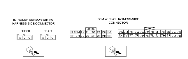
• Inspect for continuity between BCM terminal 2P or 7K (wiring harness-side) and intruder sensor terminal B (wiring harness-side)
• Is there continuity?
|
Yes
|
Go to the next step.
|
|
No
|
Repair or replace the wiring harness for a possible open circuit, then go to Step 6.
|
|
4
|
INSPECT INTRUDER SENSOR SIGNAL CIRCUIT FOR SHORT TO GND
• Inspect for continuity between BCM terminal 2P or 7K (wiring harness-side) and body GND.
• Is there continuity?
|
Yes
|
Repair or replace the wiring harness for a possible short to GND, then go to Step 6.
|
|
No
|
Go to the next step.
|
|
5
|
INSPECT INTRUDER SENSOR SIGNAL CIRCUIT FOR SHORT TO POWER SUPPLY
• Turn the ignition switch to the ON position (Engine off).
• Measure the voltage between BCM terminal 2P or 7K (wiring harness-side) and body GND.
• Is the voltage B+?
|
Yes
|
Repair or replace the wiring harness for a possible short to power supply, then go to the next step.
|
|
No
|
Replace the intruder sensor, then go to the next step.
|
|
6
|
VERIFY TROUBLESHOOTING COMPLETED
• Make sure to reconnect all disconnected connectors.
• Clear the DTC from the BCM memory using the WDS or equivalent.
• Turn the ignition switch to off then ON.
• Is the same DTC present?
|
Yes
|
Replace the BCM.
|
|
No
|
Troubleshooting completed.
|