|
1
|
RECORD VEHICLE STATUS WHEN DTC WAS DETECTED TO UTILIZE WITH REPEATABILITY VERIFICATION
• Record the freeze frame data/snapshot data.
-
Note
-
• Recording can be facilitated using the screen capture function of the PC.
|
—
|
Go to the next step.
|
|
2
|
VERIFY RELATED REPAIR INFORMATION OR SERVICE INFORMATION AVAILABILITY
• Verify related Service Bulletins, on-line repair information, or Service Information availability.
• Is any related Information available?
|
Yes
|
Perform repair or diagnosis according to the available information.
• If the vehicle is not repaired, go to the next step.
|
|
No
|
Go to the next step.
|
|
3
|
INSPECT FOR OTHER RELATED DTCs
• Perform the DTC inspection for the PCM.
• Are any other DTCs displayed?
|
Yes
|
Repair the malfunctioning location according to the applicable DTC troubleshooting.
|
|
No
|
Go to the next step.
|
|
4
|
INSPECT ENGINE OIL LEAKAGE
• Start the engine.
• Verify that there is no engine oil leakage in the hydraulic circuit.
• Is there any leakage?
|
Yes
|
Repair or replace the malfunctioning location and add genuine engine oil, then go to repair completion verification.
|
|
No
|
Go to the next step.
|
|
5
|
INSPECT ENGINE OIL LEVEL
• Inspect the engine oil level.
• Is the engine oil level sufficient?
|
Yes
|
Go to the next step.
|
|
No
|
Add genuine engine oil, then go to the next step.
|
|
6
|
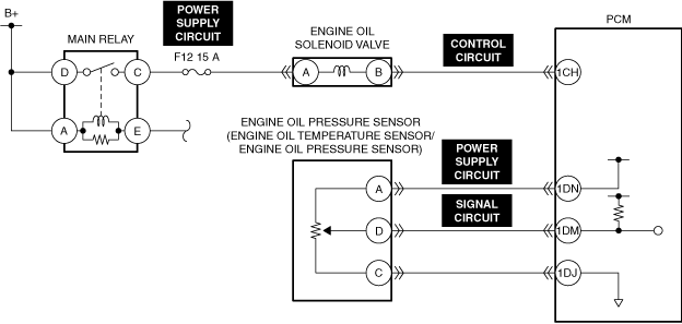
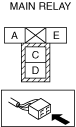
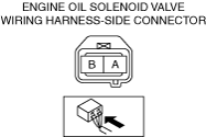
INSPECT ENGINE OIL SOLENOID VALVE CONNECTOR FOR MALFUNCTION
• Inspect the applicable connector and terminal.
• Are the connector and terminal normal?
|
Yes
|
Go to the next step.
|
|
No
|
Repair or replace the malfunctioning location and perform the repair completion verification.
|
|
7
|
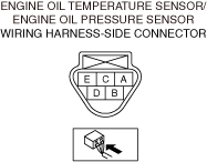
INSPECT ENGINE OIL TEMPERATURE SENSOR/ENGINE OIL PRESSURE SENSOR CONNECTOR FOR MALFUNCTION
• Inspect the applicable connector and terminal.
• Are the connector and terminal normal?
|
Yes
|
Go to the next step.
|
|
No
|
Repair or replace the malfunctioning location and perform the repair completion verification.
|
|
8
|
INSPECT F12 15 A FUSE
• Remove the F12 15 A Fuse.
• Inspect the F12 15 A Fuse.
• Is the fuse normal?
|
Yes
|
Reinstall the F12 15 A Fuse, then go to the next step.
|
|
No
|
Replace the F12 15 A Fuse and perform the repair completion verification.
|
|
9
|
INSPECT ENGINE OIL SOLENOID VALVE POWER SUPPLY CIRCUIT FOR SHORT TO GROUND OR OPEN CIRCUIT
• Inspect the applicable circuit for a short to ground or open circuit.
• Is the circuit normal?
|
Yes
|
Go to the next step.
|
|
No
|
Repair or replace the malfunctioning location and perform the repair completion verification.
|
|
10
|
INSPECT ENGINE OIL SOLENOID VALVE CONTROL CIRCUIT FOR SHORT TO GROUND OR OPEN CIRCUIT
• Inspect the applicable circuit for a short to ground or open circuit.
• Is the circuit normal?
|
Yes
|
Go to the next step.
|
|
No
|
Repair or replace the malfunctioning location and perform the repair completion verification.
|
|
11
|
INSPECT ENGINE OIL SOLENOID VALVE CIRCUIT AND ENGINE OIL PRESSURE SENSOR POWER SUPPLY CIRCUIT FOR SHORT TO GROUND
• Inspect the applicable circuit for a short to ground.
• Is the circuit normal?
|
Yes
|
Go to the next step.
|
|
No
|
Repair or replace the malfunctioning location and perform the repair completion verification.
|
|
12
|
INSPECT PCM CONNECTOR FOR MALFUNCTION
• Inspect the applicable connector and terminal.
• Are the connector and terminal normal?
|
Yes
|
Go to the next step.
|
|
No
|
Repair or replace the malfunctioning location and perform the repair completion verification.
|
|
13
|
INSPECT ENGINE OIL PRESSURE SENSOR POWER SUPPLY CIRCUIT FOR OPEN CIRCUIT
• Inspect the applicable circuit for open circuit.
• Is the circuit normal?
|
Yes
|
Go to the next step.
|
|
No
|
Repair or replace the malfunctioning location and perform the repair completion verification.
|
|
14
|
INSPECT ENGINE OIL SOLENOID VALVE FOR MALFUNCTION
• Inspect the applicable part.
• Is the part normal?
|
Yes
|
Go to the next step.
|
|
No
|
Repair or replace the malfunctioning location and perform the repair completion verification.
|
|
15
|
INSPECT ENGINE OIL PRESSURE SENSOR FOR MALFUNCTION
• Inspect the applicable part.
• Is the part normal?
|
Yes
|
Go to the next step.
|
|
No
|
Repair or replace the malfunctioning location and perform the repair completion verification.
|
|
16
|
INSPECT OIL STRAINER
• Inspect the oil strainer for clogging.
• Is there any malfunction?
|
Yes
|
Repair or replace the malfunctioning location and perform the repair completion verification.
|
|
No
|
Replace the oil pump, then go to repair completion verification.
|
|
Repair completion verification 1
|
VERIFY THAT VEHICLE IS REPAIRED
• Install/connect the part removed/disconnected during the troubleshooting procedure.
• Clear the DTC recorded in the memory.
• Replicate the vehicle conditions at the time the DTC was detected using the following procedure.
-
― Start the engine and warm it up completely.
-
Caution
-
• While performing this step, always operate the vehicle in a safe and lawful manner.
• When the M-MDS is used to observe monitor system status while driving, be sure to have another technician with you, or record the data in the M-MDS using the PID/DATA MONITOR AND RECORD capturing function and inspect later.
• Drive the vehicle under the FREEZE FRAME DATA/snapshot data condition.
• Perform the DTC inspection for the PCM.
• Is the same Pending DTC present?
|
Yes
|
Refer to the controller area network (CAN) malfunction diagnosis flow to inspect for a CAN communication error.
If the CAN communication is normal, perform the diagnosis from Step 1.
• If the malfunction recurs, replace the PCM, then go to the next step.
|
|
No
|
Go to the next step.
|
|
Repair completion verification 2
|
VERIFY IF OTHER DTCs DISPLAYED
• Perform the DTC inspection.
• Are any other DTCs displayed?
|
Yes
|
Repair the malfunctioning location according to the applicable DTC troubleshooting.
|
|
No
|
DTC troubleshooting completed.
|