|
1
|
RECORD VEHICLE STATUS WHEN DTC WAS DETECTED TO UTILIZE WITH REPEATABILITY VERIFICATION
• Record the freeze frame data/snapshot data.
-
Note
-
• Recording can be facilitated using the screen capture function of the PC.
|
—
|
Go to the next step.
|
|
2
|
VERIFY RELATED REPAIR INFORMATION OR SERVICE INFORMATION AVAILABILITY
• Verify related Service Bulletins, on-line repair information, or Service Information availability.
• Is any related Information available?
|
Yes
|
Perform repair or diagnosis according to the available information.
• If the vehicle is not repaired, go to the next step.
|
|
No
|
Go to the next step.
|
|
3
|
INSPECT FOR OTHER RELATED DTCs
• Perform the DTC inspection for the PCM.
• Are any other DTCs displayed?
|
Yes
|
Repair the malfunctioning location according to the applicable DTC troubleshooting.
|
|
No
|
Go to the next step.
|
|
4
|
INSPECT A/F SENSOR HEATER FOR MALFUNCTION
• Inspect the applicable part.
• Is the part normal?
|
Yes
|
Go to the next step.
|
|
No
|
Repair or replace the malfunctioning location and perform the repair completion verification.
|
|
5
|
INSPECT A/F SENSOR FOR MALFUNCTION
• Inspect the applicable part.
• Is the part normal?
|
Yes
|
Go to the next step.
|
|
No
|
Repair or replace the malfunctioning location and perform the repair completion verification.
|
|
6
|
INSPECT INSTALLATION OF A/F SENSOR
• Inspect installation of A/F sensor.
• Is the A/F sensor installed securely?
|
Yes
|
Go to the next step.
|
|
No
|
Repair or replace the malfunctioning location and perform the repair completion verification.
|
|
7
|
INSPECT EXHAUST SYSTEM FOR LEAKAGE
• Visually inspect for exhaust leakage in the exhaust system.
• Is there any leakage?
|
Yes
|
Repair or replace the malfunctioning part according to the inspection results, then go to repair completion verification.
|
|
No
|
Repair or replace the malfunctioning location and perform the repair completion verification.
|
|
8
|
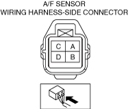
INSPECT A/F SENSOR CONNECTOR FOR MALFUNCTION
• Inspect the applicable connector and terminal.
• Are the connector and terminal normal?
|
Yes
|
Go to the next step.
|
|
No
|
Repair or replace the malfunctioning location and perform the repair completion verification.
|
|
9
|
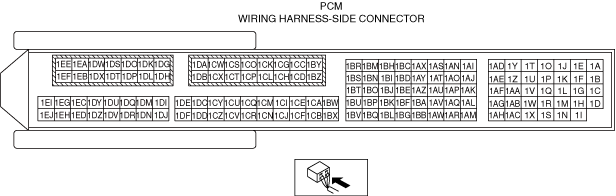
INSPECT PCM CONNECTOR FOR MALFUNCTION
• Inspect the applicable connector and terminal.
• Are the connector and terminal normal?
|
Yes
|
Go to the next step.
|
|
No
|
Repair or replace the malfunctioning location and perform the repair completion verification.
|
|
10
|
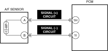
INSPECT A/F SENSOR SIGNAL (+) CIRCUIT AND SIGNAL CIRCUIT (-) FOR SHORT TO GROUND
• Inspect the applicable circuit for a short to ground.
• Is the circuit normal?
|
Yes
|
Go to the next step.
|
|
No
|
Repair or replace the malfunctioning location and perform the repair completion verification.
|
|
11
|
INSPECT A/F SENSOR SIGNAL (+) CIRCUIT AND SIGNAL CIRCUIT (-) FOR OPEN CIRCUIT
• Inspect the applicable circuit for open circuit.
• Is the circuit normal?
|
Yes
|
Go to the next step.
|
|
No
|
Repair or replace the malfunctioning location and perform the repair completion verification.
|
|
12
|
INSPECT ENGINE COMPRESSION
• Inspect the engine compression.
• Are compression pressures within specification?
|
Yes
|
Go to the next step.
|
|
No
|
Repair or replace the malfunctioning part according to the inspection results, then go to repair completion verification.
|
|
13
|
INSPECT SEALING OF ENGINE COOLANT PASSAGE
• Perform the “ENGINE COOLANT LEAKAGE INSPECTION”.
• Does the radiator cap tester needle drop even though there is no engine coolant leakage from the radiator or the hoses?
|
Yes
|
Engine coolant leakage from the engine (between the combustion chamber and the engine coolant passage) may have occurred.
• Verify the conditions of the gasket and the cylinder head.
-
― If there is any malfunction:
-
• Repair or replace the malfunctioning part according to the inspection results, then go to repair completion verification.
|
|
No
|
Go to the next step.
|
|
14
|
INSPECT FOR MALFUNCTION DUE TO INTERNAL ENGINE WEAR, DAMAGE
• Inspect for the following engine internal parts:
-
― Cylinder
― Piston ring
― Intake valve
― Exhaust valve
― Such as cylinder head gasket
• Are all items normal?
|
Yes
|
Engine internal parts are normal.
• Go to the next step.
|
|
No
|
Repair or replace the malfunctioning part according to the inspection results, then go to repair completion verification.
|
|
Repair completion verification 1
|
VERIFY THAT VEHICLE IS REPAIRED
• Install/connect the part removed/disconnected during the troubleshooting procedure.
• Clear the DTC recorded in the memory.
• Replicate the vehicle conditions at the time the DTC was detected using the following procedure.
-
― Start the engine and warm it up completely.
― Drive the vehicle on a flat road surface 5 times under the following conditions.
-
1. Drive the vehicle in third gear at 50 km/h {31 mph} while maintaining the speed for 30 s.
2. Stop the vehicle and idle the engine.
• Perform the DTC inspection for the PCM.
• Is the same Pending DTC present?
|
Yes
|
Refer to the controller area network (CAN) malfunction diagnosis flow to inspect for a CAN communication error.
If the CAN communication is normal, perform the diagnosis from Step 1.
• If the malfunction recurs, replace the PCM, then go to the next step.
|
|
No
|
Go to the next step.
|
|
Repair completion verification 2
|
VERIFY IF OTHER DTCs DISPLAYED
• Perform the DTC inspection.
• Are any other DTCs displayed?
|
Yes
|
Repair the malfunctioning location according to the applicable DTC troubleshooting.
|
|
No
|
DTC troubleshooting completed.
|