 |
am6zzw00014443
DTC P0401:00 [PCM (SKYACTIV-D)]
id0102t5704200
Details On DTCs
|
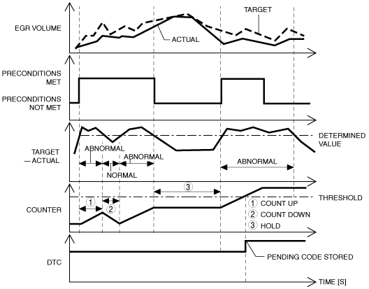
Description |
HP-EGR control system: Insufficient amount of EGR |
|
|---|---|---|
|
Detection condition
|
Determination conditions
|
• The HP-EGR volume is less than 0.2 g/rev for the target value for a continuous 8.2 s.
|
|
Preconditions
|
• During HP-EGR control
• Engine speed: 1,200―6,000 rpm
• Fuel injection amount: 4―50 mm3/st
• Engine torque: 20―240 N·m {2.1―24 kgf·m, 15―177 ft·lbf}
• The following DTCs are not detected
|
|
|
Drive cycle
|
• 2
|
|
|
Self-test type
|
• CMDTC self test
|
|
|
Sensor/unit used
|
• HP-EGR control valve
• LP-EGR control valve
• Intake shutter valve
• Exhaust shutter valve
• MAF sensor
• MAP sensor
• Boost air temperature sensor
• Exhaust gas pressure sensor No.1
• Exhaust gas temperature sensor No.1
|
|
|
Fail-safe
|
• Not applicable
|
|
|
Vehicle status when dtcs are output
|
• Check engine light turns on
|
|
|
Possible cause
|
• PCM input signal error
• Intake shutter valve malfunction
• HP-EGR control valve malfunction (stuck closed)
• Air suction from intake-air system piping (between turbocharger and intake manifold)
• HP-EGR malfunction (clogging in HP-EGR piping)
• PCM malfunction
|
|
System Wiring Diagram
Function Explanation (DTC Detection Outline)
am6zzw00014443
|
Repeatability Verification Procedure
PID Item/Simulation Item Used In Diagnosis
PID/DATA monitor item table
|
Item (definition) |
Reference |
|---|---|
|
CHARGE_AIR_COOL_TEMP
|
|
|
EX_PRES
|
|
|
EX_GAS_TEMP_1
|
|
|
MAP
|
|
|
MAF
|
Function Inspection Using M-MDS
|
Step |
Inspection |
Results |
Action |
|---|---|---|---|
|
1
|
PURPOSE: VERIFY RELATED REPAIR INFORMATION OR SERVICE INFORMATION AVAILABILITY
• Verify related Service Bulletins, on-line repair information, or Service Information availability.
• Is any related Information available?
|
Yes
|
Perform repair or diagnosis according to the available information.
• If the vehicle is not repaired, go to the next step.
|
|
No
|
Go to the next step.
|
||
|
2
|
PURPOSE: VERIFY DTC CAUSING FREEZE FRAME DATA
• Is DTC P0401:00 causing the freeze frame data?
|
Yes
|
Go to the next step.
|
|
No
|
Inspect the DTC causing the freeze frame data.
(See DTC TABLE [PCM (SKYACTIV-D)].)
|
||
|
3
|
PURPOSE: RECORD VEHICLE STATUS WHEN DTC WAS DETECTED TO UTILIZE WITH REPEATABILITY VERIFICATION
• Record the freeze frame data/snapshot data.
|
—
|
Go to the next step.
|
|
4
|
PURPOSE: VERIFY OTHER RELATED DTCs
• Perform the DTC inspection for the PCM.
(See DTC INSPECTION)
• Are any other DTCs displayed?
|
Yes
|
Repair the malfunctioning location according to the applicable DTC troubleshooting.
(See DTC TABLE [PCM (SKYACTIV-D)].)
|
|
No
|
Go to the next step.
|
||
|
5
|
PURPOSE: VERIFY RELATED SENSOR INPUT SIGNAL
• Start the engine and warm it up.
• Display the following PIDs using the M-MDS.
(See DTC INSPECTION.)
• Are the monitoring values normal?
|
Yes
|
Go to Troubleshooting Diagnostic Procedure to perform the procedure from step 1.
|
|
No
|
Go to the next step.
|
||
|
6
|
PURPOSE: INSPECT WIRING HARNESSES AND CONNECTORS FOR RELATED-SENSOR
• Display the following PIDs using the M-MDS.
(See DTC INSPECTION)
• When the PCM, MAF sensor, MAP sensor, boost air temperature sensor, exhaust gas pressure sensor No.1, and exhaust gas temperature sensor No.1 connectors are shaken, does the PID value include a PID item which has changed?
|
Yes
|
Inspect the related wiring harnesses and connectors.
• Repair or replace the malfunctioning location.
Go to the troubleshooting procedure to perform the procedure from repair completion verification.
|
|
No
|
Go to Troubleshooting Diagnostic Procedure to perform the procedure from step 1.
|
Troubleshooting Diagnostic Procedure
|
Step |
Inspection |
Results |
Action |
|---|---|---|---|
|
1
|
PURPOSE: INSPECT INTAKE SHUTTER VALVE FOR MALFUNCTION
• Inspect the applicable part.
• Is the part normal?
|
Yes
|
Go to the next step.
|
|
No
|
Repair or replace the malfunctioning location and perform the repair completion verification.
|
||
|
2
|
PURPOSE: VERIFY HP-EGR CONTROL VALVE OPERATION CONDITION
• Perform the HP-EGR control inspection.
• Is the HP-EGR control valve operation normal?
|
Yes
|
Go to the next step.
|
|
No
|
Repair or replace the malfunctioning location and perform the repair completion verification.
|
||
|
3
|
PURPOSE: INSPECT INTAKE AIR SYSTEM FOR AIR SUCTION
• Visually inspect the following parts of the intake air system for looseness or damage.
• Is the intake air system normal?
|
Yes
|
Go to the next step.
|
|
No
|
Repair or replace the malfunctioning location and perform the repair completion verification.
|
||
|
4
|
PURPOSE: INSPECT HP-EGR PASSAGE FOR CLOGGING
• Switch the ignition OFF.
• Remove the HP-EGR control valve.
• Is the gasket correctly installed? Visually inspect the HP-EGR passage for clogging.
• Is the HP-EGR passage normal?
|
Yes
|
Go to the next step.
|
|
No
|
Repair or replace the malfunctioning location, then go to the next step.
(If there is clogging caused by soot in the HP-EGR control valve, inspect around the HP-EGR piping and clean or replace it)
|
||
|
Repair completion verification 1
|
PURPOSE: VERIFY THAT VEHICLE IS REPAIRED
• Install/connect the part removed/disconnected during the troubleshooting procedure.
• Clear the DTC recorded in the memory.
(See CLEARING DTC.)
• Replicate the vehicle conditions at the time the DTC was detected using the following procedure.
• Perform the DTC inspection for the PCM.
(See DTC INSPECTION.)
• Is the same Pending DTC present?
|
Yes
|
Refer to the controller area network (CAN) malfunction diagnosis flow to inspect for a CAN communication error.
If the CAN communication is normal, perform the diagnosis from Step 1.
• If the malfunction recurs, replace the PCM, then go to the next step.
|
|
No
|
Go to the next step.
|
||
|
Repair completion verification 2
|
PURPOSE: VERIFY IF OTHER DTCs DISPLAYED
• Perform the DTC inspection.
(See DTC INSPECTION.)
• Are any other DTCs displayed?
|
Yes
|
Repair the malfunctioning location according to the applicable DTC troubleshooting.
|
|
No
|
DTC troubleshooting completed.
|