ac3wzw00005366
|
DTC P2000:00 [PCM (SKYACTIV-D)]
id0102t5721100
Details On DTCs
|
Description |
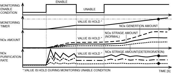
NOx absorber efficiency below threshold |
|
|---|---|---|
|
Detection condition
|
Determination conditions
|
• If the NOx purification rate detected by the NOx sensor is less than the NOx reduction rate of the threshold value calculated by the PCM from the engine operation conditions, the PCM determines that there is a malfunction in the NSC (NOx Storage Catalyst) efficiency.
|
|
Preconditions
|
• All of the following conditions are met (basic condition)
• After all of the basic conditions have been met, a cumulative 30 s or more have elapsed since all of the following conditions have been met.
• The following DTCs are not detected.
|
|
|
Drive cycle
|
• 2
|
|
|
Self test type
|
• CMDTC self test
|
|
|
Sensor used
|
• NOx sensor
• MAF sensor
• Exhaust pressure sensor No.1
• Exhaust temperature sensor No.1
• Exhaust temperature sensor No.2
• Exhaust temperature sensor No.3
• IAT sensor No.3
• MAP sensor
• PCM
|
|
|
Fail-safe
|
• Not applicable
|
|
|
Vehicle status when dtcs are output
|
• Illuminates check engine light.
|
|
|
Possible cause
|
• Fuel injection system malfunction
• NSC (NOx Storage Catalyst) malfunction
• PCM malfunction
|
|
System Wiring Diagram
Function Explanation (DTC Detection Outline)
ac3wzw00005366
|
Repeatability Verification Procedure
1. Start the engine.
2. Drive the vehicle for 10 min under the driving conditions stored in the FREEZE FRAME DATA/snapshot data.
PID Item/Simulation Item Used In Diagnosis
PID/DATA monitor item table
|
Item |
Reference |
|---|---|
|
MAF
|
|
|
EX_PRES
|
|
|
EX_GAS_TEMP_1
|
|
|
EX_GAS_TEMP_2
|
|
|
EX_GAS_TEMP_3
|
|
|
IAT13
|
|
|
MAP
|
Function Inspection Using M-MDS
|
Step |
Inspection |
Results |
Action |
|---|---|---|---|
|
1
|
PURPOSE: VERIFY RELATED REPAIR INFORMATION OR SERVICE INFORMATION AVAILABILITY
• Verify related Service Bulletins, on-line repair information, or Service Information availability.
• Is any related Information available?
|
Yes
|
Perform repair or diagnosis according to the available information.
• If the vehicle is not repaired, go to the next step.
|
|
No
|
Go to the next step.
|
||
|
2
|
PURPOSE: VERIFY DTC CAUSING FREEZE FRAME DATA
• Is DTC P2000:00 causing the freeze frame data?
|
Yes
|
Go to the next step.
|
|
No
|
Inspect the DTC causing the freeze frame data.
(See DTC TABLE [PCM (SKYACTIV-D)].)
|
||
|
3
|
PURPOSE: RECORD VEHICLE STATUS WHEN DTC WAS DETECTED TO UTILIZE WITH REPEATABILITY VERIFICATION
• Record the freeze frame data/snapshot data.
|
—
|
Go to the next step.
|
|
4
|
PURPOSE: VERIFY OTHER RELATED DTCs
• Perform the DTC inspection for the PCM.
(See DTC INSPECTION)
• Are any other DTCs displayed?
|
Yes
|
Repair the malfunctioning location according to the applicable DTC troubleshooting.
(See DTC TABLE [PCM (SKYACTIV-D)].)
|
|
No
|
Go to the next step.
|
||
|
5
|
PURPOSE: VERIFY IF THERE IS PID ITEM CAUSING DRASTIC CHANGES OF ACCELERATION FLUCTUATION BY INPUT SIGNAL TO PCM OR PCM
• Access the following PIDs using the M-MDS:
(See PID/DATA MONITOR INSPECTION.)
• Is there any signal that is far out of specification?
|
Yes
|
Go to the next step.
|
|
No
|
Go to Troubleshooting Diagnostic Procedure to perform the procedure from step 1.
|
||
|
6
|
PURPOSE: VERIFY CONNECTOR CONNECTIONS
• Access the following PIDs using the M-MDS:
(See PID/DATA MONITOR INSPECTION.)
• When the following parts are shaken, does the PID value include a PID item which has changed?
|
Yes
|
Inspect the related wiring harness and connector.
• Repair or replace the malfunctioning part.
Go to the troubleshooting procedure to perform the procedure from repair completion verification.
|
|
No
|
Go to Troubleshooting Diagnostic Procedure to perform the procedure from step 1.
|
Troubleshooting Diagnostic Procedure
|
Step |
Inspection |
Results |
Action |
|---|---|---|---|
|
1
|
PURPOSE: INSPECT NOx SENSOR FOR MALFUNCTION
• Inspect the applicable part.
• Is the part normal?
|
Yes
|
Go to the next step.
|
|
No
|
Repair or replace the malfunctioning location and perform the repair completion verification.
|
||
|
2
|
PURPOSE: DETERMINE IF MALFUNCTION CAUSE IS FUEL INJECTION SYSTEM OR DETERIORATION OF CATALYTIC CONVERTER (OXIDATION CATALYST/NOX STRAGE CATALYST)
• Perform the fuel injector operation Inspection.
• Is there any malfunction?
|
Yes
|
Repair or replace the malfunctioning part according to the inspection results.
Then go to the next step.
|
|
No
|
Replace the catalytic converter (oxidation catalyst/NOx strage catalyst), then go to the next step.
|
||
|
Repair completion verification 1
|
PURPOSE: VERIFY THAT VEHICLE IS REPAIRED
• Install/connect the part removed/disconnected during the troubleshooting procedure.
• Clear the DTC recorded in the memory.
(See CLEARING DTC.)
• Replicate the vehicle conditions at the time the DTC was detected using the following procedure.
• Perform the DTC inspection for the PCM.
(See DTC INSPECTION.)
• Is the same Pending DTC present?
|
Yes
|
Refer to the controller area network (CAN) malfunction diagnosis flow to inspect for a CAN communication error.
If the CAN communication is normal, perform the diagnosis from Step 1.
• If the malfunction recurs, replace the PCM, then go to the next step.
|
|
No
|
Go to the next step.
|
||
|
Repair completion verification 2
|
PURPOSE: VERIFY IF OTHER DTCs DISPLAYED
• Perform the DTC inspection.
(See DTC INSPECTION.)
• Are any other DTCs displayed?
|
Yes
|
Repair the malfunctioning location according to the applicable DTC troubleshooting.
|
|
No
|
DTC troubleshooting completed.
|