 |
ac30zw00005269
EXHAUST SYSTEM REMOVAL/INSTALLATION [SKYACTIV-D 1.8]
id0115q9800200
Replacement Part
|
Gasket
Quantity: 1
Location of use: Main silencer
|
Nut
Quantity: 4
Location of use: Ammonia slip catalyst
|
Gasket
Quantity: 1
Location of use: Ammonia slip catalyst
|
|
Gasket
Quantity: 1
Location of use: Catalytic converter (Diesel particulate filter)
|
Gasket
Quantity: 1
Location of use: Catalytic converter (oxidation catalyst/NOx strage catalyst)
|
Exhaust gas pressure sensor No.2 hose
Quantity: 2
Location of use: Catalytic converter (Diesel particulate filter)
|
|
Clamp
Quantity: 2
Location of use: Catalytic converter (Diesel particulate filter)
|
—
|
—
|
Catalytic Converter (Diesel particulate filter) Replacement Procedure
1. If the catalytic converter (Diesel particulate filter) is replaced, perform the following procedure.
|
STEP |
ACTION |
PAGE/CONDITION |
|---|---|---|
|
1
|
Perform Diesel particulate filter data reset procedure.
|
|
|
2
|
Switch the ignition off.
|
—
|
|
3
|
Wait for 30 s or more.
|
—
|
|
4
|
Switch the ignition ON (engine off).
|
—
|
|
5
|
Perform KOEO self-test procedure.
|
(See DTC INSPECTION.)
|
|
6
|
Perform KOER self-test procedure.
|
(See DTC INSPECTION.)
|
|
7
|
Perform compulsory diesel particulate filter regeneration.
|
|
|
8
|
Clear the DTCs.
|
(See CLEARING DTC.)
|
Exhaust Shutter Valve Replacement Procedure
1. If the exhaust shutter valve is replaced, perform the following procedure.
|
STEP |
ACTION |
PAGE/CONDITION |
|---|---|---|
|
1
|
Perform exhaust shutter valve initialization procedure.
|
|
|
2
|
Warm the engine until the engine coolant temperature is 70 degrees C.
|
—
|
|
3
|
Switch the ignition off.
|
—
|
|
4
|
Wait for 30 s or more.
|
—
|
|
5
|
Start the engine.
|
—
|
|
6
|
Maintain the engine idling condition for 10 s.
|
—
|
|
7
|
Switch the ignition off.
|
—
|
|
8
|
Wait for 30 s or more.
|
—
|
|
9
|
Perform KOEO self-test procedure.
|
(See DTC INSPECTION.)
|
|
10
|
Perform KOER self-test procedure.
|
(See DTC INSPECTION.)
|
Exhaust System Removal /Installation
1. Disconnect the negative battery terminal. (See NEGATIVE BATTERY TERMINAL DISCONNECTION/CONNECTION [(E)].)
2. Remove the front under cover No.2. (See FRONT UNDER COVER No.2 REMOVAL/INSTALLATION.)
3. Drain the engine coolant. (See ENGINE COOLANT REPLACEMENT [SKYACTIV-D 1.8].)
4. Remove in the order shown in the figure.
5. Remove the exhaust system insulator. (See Exhaust system insulator removal/installation.)
6. Install in the reverse order of removal.
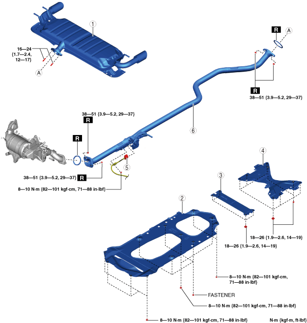
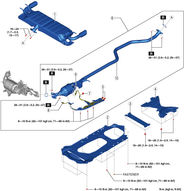
Step 1 (European (L.H.D. U.K.) specs.(2WD))
ac30zw00005269
|
|
1
|
Main silencer
|
|
2
|
Tunnel cover
|
|
3
|
Brace bar
(See Brace bar installation note.)
|
|
4
|
Tunnel member
|
|
5
|
Connector
|
|
6
|
Ammonia slip catalyst component
|
|
7
|
Exhaust shutter valve connector
|
|
8
|
NOx sensor
|
|
9
|
PM sensor
|
|
10
|
Ammonia slip catalyst
|
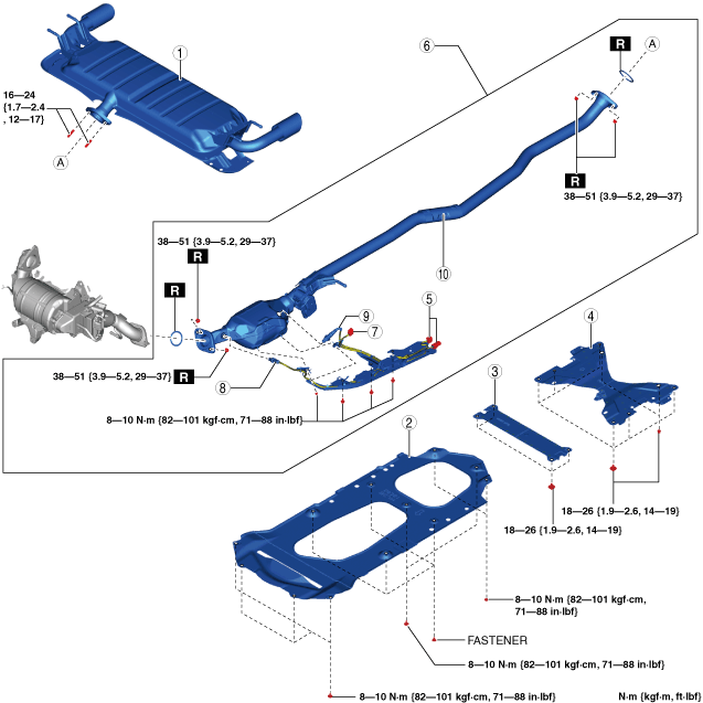
Step 1 (Except European (L.H.D. U.K.) specs. (2WD))
ac30zw00003914
|
|
1
|
Main silencer
|
|
2
|
Tunnel cover
|
|
3
|
Brace bar
(See Brace bar installation note.)
|
|
4
|
Tunnel member
|
|
5
|
Exhaust shutter valve connector
|
|
6
|
Middle pipe
|
Step 1 (European (L.H.D. U.K.) specs.(AWD))
ac30zw00002243
|
|
1
|
Main silencer
|
|
2
|
Tunnel cover
|
|
3
|
Brace bar
(See Brace bar installation note.)
|
|
4
|
Tunnel member
|
|
5
|
Connector
|
|
6
|
Ammonia slip catalyst component
|
|
7
|
Exhaust shutter valve connector
|
|
8
|
NOx sensor
|
|
9
|
PM sensor
|
|
10
|
Ammonia slip catalyst
|
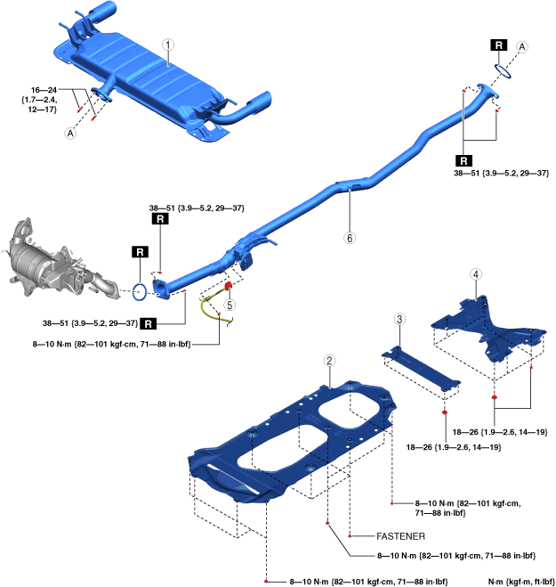
Step 1 (Except European (L.H.D. U.K.) specs. (AWD))
ac30zw00003915
|
|
1
|
Main silencer
|
|
2
|
Tunnel cover
|
|
3
|
Brace bar
(See Brace bar installation note.)
|
|
4
|
Tunnel member
|
|
5
|
Exhaust shutter valve connector
|
|
6
|
Middle pipe
|
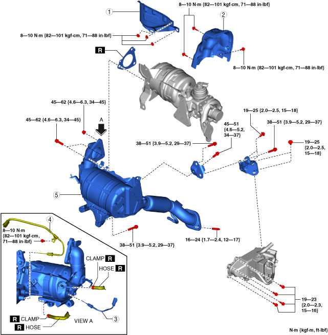
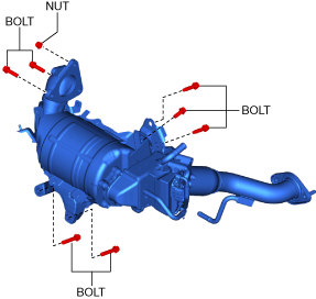
Step 2
ac30zw00004973
|
|
1
|
Insulator
|
|
2
|
Catalytic converter (Diesel particulate filter) insulator
|
|
3
|
Exhaust gas temperature sensor No.3
|
|
4
|
Exhaust gas temperature sensor No.4 (European (L.H.D. U.K.) specs.)
|
|
5
|
Catalytic converter (Diesel particulate filter)
|
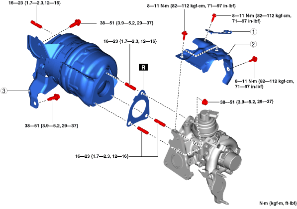
Step 3
ac30zw00002245
|
|
1
|
A/F sensor wiring harness bracket
|
|
2
|
Turbocharger insulator
|
|
3
|
Catalytic converter (oxidation catalyst/NOx strage catalyst)
|
Exhaust system insulator removal/installation
1. Remove the floor under cover No.1 (RH). (See FLOOR UNDER COVER REMOVAL/INSTALLATION.)
2. Remove the floor under cover No.2. (See FLOOR UNDER COVER REMOVAL/INSTALLATION.)
3. Remove in the order shown in the figure.
4. Install in the reverse order of removal.
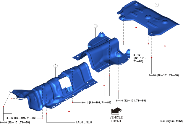
2WD
ac30zw00002246
|
|
1
|
Insulator (rear)
|
|
2
|
Insulator (front)
|
|
3
|
Insulator (middle)
|
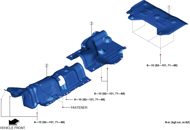
AWD
ac30zw00003916
|
|
1
|
Insulator (rear)
|
|
2
|
Insulator (front)
|
|
3
|
Insulator (middle)
|
Ammonia slip catalyst component removal note
1. Remove the floor under cover No.1 (LH). (See FLOOR UNDER COVER REMOVAL/INSTALLATION.)
2. Remove the ammonia slip catalyst component.
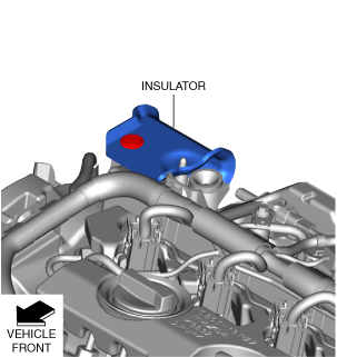
Catalytic converter (Diesel particulate filter) insulator removal note
1. Remove the engine cover. (See ENGINE COVER REMOVAL/INSTALLATION [SKYACTIV-D 1.8].)
2. Remove the insulator shown in the figure.
ac3wzw00004757
|
3. Remove the windshield wiper arm and blade. (See WINDSHIELD WIPER ARM AND BLADE REMOVAL/INSTALLATION.)
4. Remove the cowl grille. (See COWL GRILLE REMOVAL/INSTALLATION.)
5. Remove the windshield wiper motor and link. (See WINDSHIELD WIPER MOTOR AND LINK REMOVAL/INSTALLATION.)
6. Remove the cowl panel. (See COWL PANEL REMOVAL/INSTALLATION [(E)].)
7. Remove the catalytic converter (Diesel particulate filter) insulator.
Catalytic converter (Diesel particulate filter) removal note
1. Remove the front crossmember. (See FRONT CROSSMEMBER REMOVAL/INSTALLATION [(E)].)
2. Remove the battery and the battery tray. (See BATTERY REMOVAL/INSTALLATION [SKYACTIV-D 1.8].)
3. Disconnect the LP-EGR pipe from the turbocharger air inlet hose. (See LP-EGR CONTROL VALVE REMOVAL/INSTALLATION [SKYACTIV-D 1.8].)
4. Disconnect the front drive shaft (RH) from the transaxle side and set is aside so that it does not interfere with the servicing. (See FRONT DRIVE SHAFT REMOVAL/INSTALLATION [(E)].)
5. Remove the drive shaft bracket. (See FRONT DRIVE SHAFT REMOVAL/INSTALLATION [(E)].)
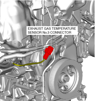
6. Disconnect exhaust gas temperature sensor No.3 connector shown in the figure.(See EXHAUST GAS TEMPERATURE SENSOR REMOVAL/INSTALLATION [SKYACTIV-D 1.8].)
ac3wzw00004758
|
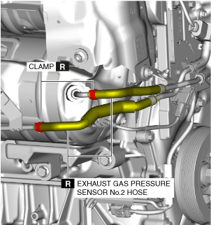
7. Disconnect the exhaust gas pressure sensor No.2 hose on the catalytic converter (Diesel particulate filter) side shown in the figure.(See EXHAUST GAS PRESSURE SENSOR REMOVAL/INSTALLATION [SKYACTIV-D 1.8].)
ac30zw00004974
|
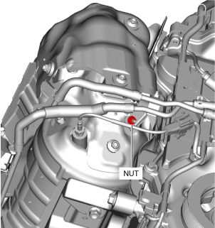
8. Remove the nut shown in the figure and set the bracket aside.
ac3wzw00004760
|
9. Disconnect the connectors of the following parts:
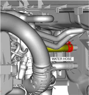
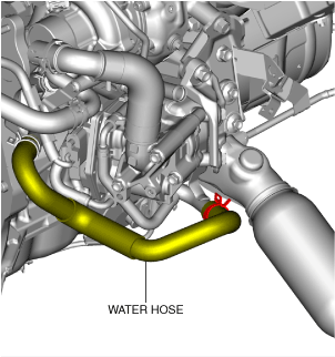
10. Disconnect the water hose shown in the figure.
ac3wzw00004761
|
11. Disconnect the water hose shown in the figure.
ac3wzw00004762
|
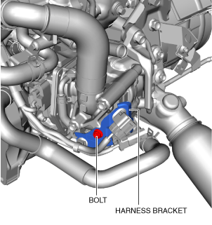
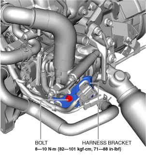
12. Remove the bolts shown in the figure and set the wiring harness bracket aside. (European (L.H.D. U.K.) specs.)
ac3wzw00004763
|
13. Remove the catalytic converter (Diesel particulate filter).
Catalytic converter (oxidation catalyst/NOx strage catalyst) installation note
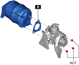
1. Temporarily tighten the nuts shown in the figure until they contact the opposing part.
ac3wzw00004764
|
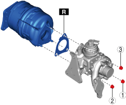
2. Install the nuts in the order shown in the figure.
ac3wzw00004765
|
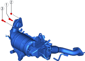
Catalytic converter (Diesel particulate filter) installation note
1. Temporarily tighten the bolts and nuts shown in the figure until they contact the opposing part.
ac30zw00002248
|
2. Install the bolts and nuts in the order shown in the figure.
ac3wzw00004767
|
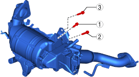
3. Temporarily tighten the bolts in the order shown in the figure.
ac3wzw00004768
|
4. Temporarily tighten the bolts in the order shown in the figure.
ac30zw00002249
|
5. Install the harness bracket shown in the figure. (European (L.H.D. U.K.) specs.)
ac3wzw00004770
|
6. Install the water hose shown in the figure.
ac3wzw00004771
|
7. Install the water hose shown in the figure.
ac3wzw00004761
|
8. Connect the connectors of the following parts:
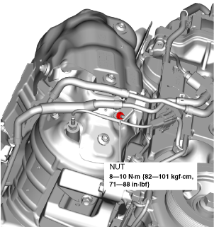
9. Install the nut shown in the figure.
ac3wzw00004772
|
10. Connect the hose of the exhaust gas pressure sensor No.2 shown in the figure.
ac3wzw00004773
|
11. Connect the hose of the exhaust gas temperature sensor No.3 connector shown in the figure.
ac3wzw00004758
|
12. Install the drive shaft bracket. (See FRONT DRIVE SHAFT REMOVAL/INSTALLATION [(E)].)
13. Install the drive shaft (RH). (See FRONT DRIVE SHAFT REMOVAL/INSTALLATION [(E)].)
14. Install the LP-EGR pipe. (See LP-EGR CONTROL VALVE REMOVAL/INSTALLATION [SKYACTIV-D 1.8].)
15. Install the battery and the battery tray. (See BATTERY REMOVAL/INSTALLATION [SKYACTIV-D 1.8].)
16. Install the front crossmember. (See FRONT CROSSMEMBER REMOVAL/INSTALLATION [(E)].)
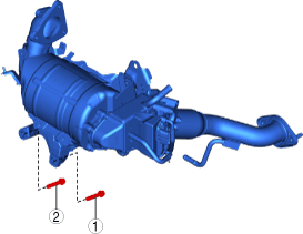
Catalytic converter (Diesel particulate filter) insulator installation note
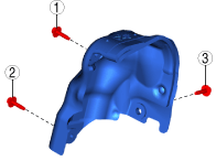
1. Temporarily tighten the bolts shown in the figure until they contact the opposing part.
ac3wzw00004774
|
2. Temporarily tighten the bolts in the order shown in the figure.
ac3wzw00004775
|
3. Install the cowl panel. (See COWL PANEL REMOVAL/INSTALLATION [(E)].)
4. Install the windshield wiper motor and link. (See WINDSHIELD WIPER MOTOR AND LINK REMOVAL/INSTALLATION.)
5. Install the cowl grille. (See COWL GRILLE REMOVAL/INSTALLATION.)
6. Install the windshield wiper arm and blade. (See WINDSHIELD WIPER ARM AND BLADE REMOVAL/INSTALLATION.)
7. Install the insulator shown in the figure.
ac3wzw00004757
|
8. Install the engine cover. (See ENGINE COVER REMOVAL/INSTALLATION [SKYACTIV-D 1.8].)
Insulator (middle) installation note
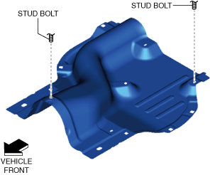
1. Align the stud bolts shown in the figure with the insulator (middle) and install.
2WD
ac30zw00002250
|
AWD
ac30zw00005301
|
2. Tighten the nuts to the specified torque.
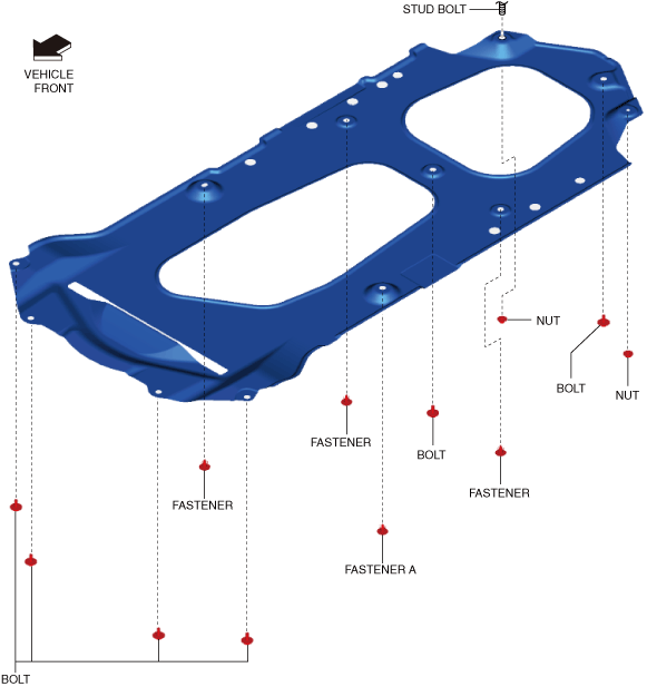
Insulator (front) installation note
1. Align the stud bolts shown in the figure with the insulator (front) and install.
am3zzw00021201
|
2. Install the fasteners.
3. Tighten the nuts to the specified torque.
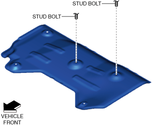
Insulator (rear) installation note
1. Align the stud bolt shown in the figure with the insulator (rear) and install.
ac30zw00002252
|
2. Tighten the nuts to the specified torque.
Tunnel member installation note
1. Tighten bolt A shown in the figure to the specified torque.
ac30zw00004648
|
2. Tighten bolt B shown in the figure to the specified torque.
3. Tighten the remaining bolts and nuts to the specified torque.
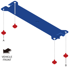
Brace bar installation note
1. Tighten bolt A shown in the figure to the specified torque.
ac30zw00004649
|
2. Tighten bolt B shown in the figure to the specified torque.
3. Tighten the remaining bolts to the specified torque.
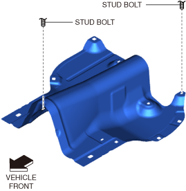
Tunnel cover installation note
1. Align the stud bolt shown in the figure with the tunnel cover and install.
ac30zw00002255
|
2. Install fastener A shown in the figure.
3. Install the remaining fasteners.
4. Tighten the bolts shown in the figure to the specified torque.
5. Tighten the nuts shown in the figure to the specified torque.