DTC P2200:00 [PCM (SKYACTIV-D)]
id0102t5725700
Details On DTCs
|
Description |
NOx sensor control circuit range/performance problem |
|
|---|---|---|
|
Detection condition
|
Determination conditions
|
• Any one of the following conditions is met:
|
|
Preconditions
|
• Battery voltage: 10.9—16 V
• CAN communication is normal at engine start for a continuous 20 s or more
• The following DTCs is not detected:
|
|
|
Drive cycle
|
• 1
|
|
|
Self test type
|
• CMDTC self test
|
|
|
Sensor used
|
• NOx sensor
• PCM
|
|
|
Fail-safe
|
• Not applicable
|
|
|
Vehicle status when dtcs are output
|
• DTC P2BAF:00 is also stored in the PCM and the vehicle speed is restricted.
|
|
|
Possible cause
|
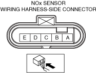
• NOx sensor connector or terminals malfunction
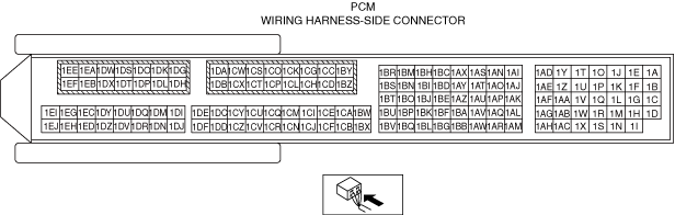
• PCM connector or terminals malfunction
• NOx sensor loose
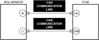
• Open or short in NOx sensor CAN communication line
• NOx sensor malfunction
• PCM malfunction
|
|
System Wiring Diagram
|
|
|
|
|
Function Explanation (DTC Detection Outline)
Repeatability Verification Procedure
1. Perform the "COMPULSORY DIESEL PARTICULATE FILTER REGENERATION". (See COMPULSORY DIESEL PARTICULATE FILTER REGENERATION [SKYACTIV-D 1.8].)
2. Idle the engine for 1 min.
PID Item/Simulation Item Used In Diagnosis
Function Inspection Using M-MDS
|
Step |
Inspection |
Results |
Action |
|---|---|---|---|
|
1
|
PURPOSE: VERIFY RELATED REPAIR INFORMATION OR SERVICE INFORMATION AVAILABILITY
• Verify related Service Bulletins, on-line repair information, or Service Information availability.
• Is any related Information available?
|
Yes
|
Perform repair or diagnosis according to the available information.
• If the vehicle is not repaired, go to the next step.
|
|
No
|
Go to the next step.
|
||
|
2
|
PURPOSE: INSPECT FOR OTHER RELATED DTCs
• Perform the DTC inspection for the PCM.
(See DTC INSPECTION.)
• Are any of the following DTCs displayed?
|
Yes
|
Repair the malfunctioning location according to the applicable DTC troubleshooting.
|
|
No
|
Go to the next step.
|
||
|
3
|
PURPOSE: RECORD VEHICLE STATUS WHEN DTC WAS DETECTED TO UTILIZE WITH REPEATABILITY VERIFICATION
• Record the freeze frame data/snapshot data.
|
—
|
Go to Troubleshooting Diagnostic Procedure to perform the procedure from Step 1.
|
Troubleshooting Diagnostic Procedure
|
Step |
Inspection |
Results |
Action |
|---|---|---|---|
|
1
|
PURPOSE: INSPECT INSTALLATION OF NOx SENSOR
• Inspect installation of NOx sensor.
• Is the NOx sensor installed securely?
|
Yes
|
Go to the next step.
|
|
No
|
Retighten the NOx sensor, then go to repair completion verification.
|
||
|
2
|
INSPECT NOx SENSOR CAN COMMUNICATION LINE FOR SHORT OR OPEN CIRCUITT
• Inspect the applicable circuit for short or open circuit.
(See CIRCUIT INSPECTION.)
• Is the circuit normal?
|
Yes
|
Replace the NOx sensor, then go to the next step.
|
|
No
|
Repair or replace the malfunctioning location and perform the repair completion verification.
|
||
|
Repair completion verification 1
|
PURPOSE: VERIFY THAT VEHICLE IS REPAIRED
• Install/connect the part removed/disconnected during the troubleshooting procedure.
• Clear the DTC recorded in the memory.
(See CLEARING DTC.)
• Replicate the vehicle conditions at the time the DTC was detected using the following procedure.
• Perform the DTC inspection for the PCM.
(See DTC INSPECTION.)
• Is the same Pending DTC present?
|
Yes
|
Refer to the controller area network (CAN) malfunction diagnosis flow to inspect for a CAN communication error.
If the CAN communication is normal, perform the diagnosis from Step 1.
• If the malfunction recurs, replace the PCM, then go to the next step.
|
|
No
|
Go to the next step.
|
||
|
Repair completion verification 2
|
PURPOSE: VERIFY IF OTHER DTCs DISPLAYED
• Perform the DTC inspection.
(See DTC INSPECTION.)
• Are any other DTCs displayed?
|
Yes
|
Repair the malfunctioning location according to the applicable DTC troubleshooting.
|
|
No
|
DTC troubleshooting completed.
|