|
1
|
DETERMINE IF MALFUNCTION CAUSE IS SHORT TO GROUND CIRCUIT OR OTHER PART
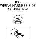
• Inspect for continuity between the integrated starter generator (ISG) terminal 2A (wiring harness-side) and body ground without disconnecting the connector.
• Is there continuity?
|
Yes
|
Go to the next step.
|
|
No
|
Intermittent concern exists.
• Explain to the customer that the malfunction is caused by an increase in the Mazda M Hybrid battery temperature. (This can be used if temperature decreases)
• Perform the repair completion verification.
|
|
2
|
PURPOSE: VERIFY IF POOR CONNECTION OF INTEGRATED STARTER GENERATOR (ISG) AFFECTS DIAGNOSTIC RESULTS
• Inspect the connection condition (part installation condition, connector connection condition) for the integrated starter generator (ISG).
• Is the connection condition (part installation condition, connector connection condition) for each part normal?
|
Yes
|
Go to the next step.
|
|
No
|
Connect each part or the connector correctly, then go to Step 14.
|
|
3
|
PURPOSE: INSPECT INTEGRATED STARTER GENERATOR (ISG) CONNECTOR FOR MALFUNCTION
• Inspect the applicable connector and terminal.
• Are the connector and terminal normal?
|
Yes
|
Go to the next step.
|
|
No
|
Repair or replace the malfunctioning location, then go to Step 14.
|
|
4
|
PURPOSE: INSPECT INTEGRATED STARTER GENERATOR (ISG) INTERNAL CIRCUIT FOR SHORT TO GROUND
• Inspect for continuity between the integrated starter generator (ISG) terminal 2A (parts-side) and body ground.
• Is there continuity?
|
Yes
|
Replace the integrated starter generator (ISG), then go to Step 14.
|
|
No
|
Go to the next step.
|
|
5
|
PURPOSE: VERIFY IF POOR CONNECTION OF DC-DC CONVERTER (Mazda M Hybrid) AFFECTS DIAGNOSTIC RESULTS
• Inspect the connection condition (part installation condition, connector connection condition) for the DC-DC converter (Mazda M Hybrid).
• Is the connection condition (part installation condition, connector connection condition) for each part normal?
|
Yes
|
Go to the next step.
|
|
No
|
Connect each part or the connector correctly, then go to Step 14.
|
|
6
|
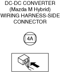
PURPOSE: INSPECT DC-DC CONVERTER (Mazda M Hybrid) CONNECTOR FOR MALFUNCTION
• Inspect the applicable connector and terminal.
• Are the connector and terminal normal?
|
Yes
|
Go to the next step.
|
|
No
|
Repair or replace the malfunctioning location, then go to Step 14.
|
|
7
|
PURPOSE: INSPECT DC-DC CONVERTER (Mazda M Hybrid) INTERNAL CIRCUIT FOR SHORT TO GROUND
• Inspect for continuity between the DC-DC converter (Mazda M Hybrid) terminal 2A (parts-side) and body ground.
• Is there continuity?
|
Yes
|
Replace the DC-DC converter (Mazda M Hybrid), then go to Step 14.
|
|
No
|
Without seat warmer system:
• Go to Step 11.
With seat warmer system:
• Go to the next step.
|
|
8
|
PURPOSE: VERIFY IF POOR CONNECTION OF SEAT WARMER CONTROL UNIT (WITHOUT POSITION MEMORY SYSTEM)/POSITION MEMORY CONTROL MODULE (WITH POSITION MEMORY SYSTEM) AFFECTS DIAGNOSTIC RESULTS
• Inspect the connection condition (part installation condition, connector connection condition) for the seat warmer control unit (without position memory system)/position memory control module (with position memory system).
• Is the connection condition (part installation condition, connector connection condition) for each part normal?
|
Yes
|
Go to the next step.
|
|
No
|
Connect each part or the connector correctly, then go to Step 14.
|
|
9
|
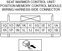
PURPOSE: INSPECT SEAT WARMER CONTROL UNIT (WITHOUT POSITION MEMORY SYSTEM)/POSITION MEMORY CONTROL MODULE (WITH POSITION MEMORY SYSTEM) CONNECTOR FOR MALFUNCTION
• Inspect the applicable connector and terminal.
• Are the connector and terminal normal?
|
Yes
|
Go to the next step.
|
|
No
|
Repair or replace the malfunctioning location, then go to Step 14.
|
|
10
|
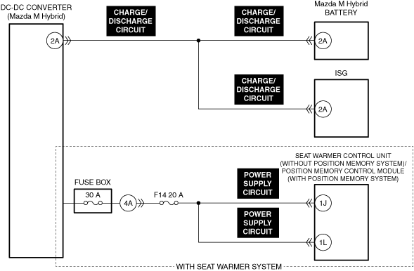
PURPOSE: INSPECT SEAT WARMER CONTROL UNIT (WITHOUT POSITION MEMORY SYSTEM)/POSITION MEMORY CONTROL MODULE (WITH POSITION MEMORY SYSTEM) POWER SUPPLY CIRCUIT FOR SHORT TO GROUND
• Inspect the power supply circuit for a short to ground.
• Is the circuit normal?
|
Yes
|
Go to the next step.
|
|
No
|
Repair or replace the malfunctioning location, then go to Step 14.
|
|
11
|
PURPOSE: VERIFY IF POOR CONNECTION OF Mazda M Hybrid BATTERY AFFECTS DIAGNOSTIC RESULTS
• Inspect the connection condition (part installation condition, connector connection condition) for the Mazda M Hybrid battery.
• Is the connection condition (part installation condition, connector connection condition) for each part normal?
|
Yes
|
Go to the next step.
|
|
No
|
Connect each part or the connector correctly, then go to Step 14.
|
|
12
|
PURPOSE: INSPECT Mazda M Hybrid BATTERY CONNECTOR FOR MALFUNCTION
• Inspect the applicable connector and terminal.
• Are the connector and terminal normal?
|
Yes
|
Go to the next step.
|
|
No
|
Repair or replace the malfunctioning location, then go to Step 14.
|
|
13
|
PURPOSE: INSPECT DC-DC CONVERTER (Mazda M Hybrid), Mazda M Hybrid BATTERY, AND INTEGRATED STARTER GENERATOR (ISG) CHARGE/DISCHARGE CIRCUIT FOR SHORT TO GROUND
• Inspect the charge/discharge circuit for a short to ground.
• Is the circuit normal?
|
Yes
|
Go to the next step.
|
|
No
|
Repair or replace the malfunctioning location, then go to the next step.
|
|
14
|
PURPOSE: VERIFY INTEGRATED STARTER GENERATOR (ISG) DTCs
• Perform the DTC inspection for the integrated starter generator (ISG).
• Are any other DTCs displayed?
|
Yes
|
Repair the malfunctioning location according to the applicable DTC troubleshooting.
|
|
No
|
Perform the repair completion verification.
|
|
Repair completion verification 1
|
PURPOSE: VERIFY THAT VEHICLE IS REPAIRED
• Install/connect the part removed/disconnected during the troubleshooting procedure.
• Clear the DTC recorded in the memory.
• Replicate the vehicle conditions at the time the DTC was detected using the following procedure.
-
― Implement the repeatability verification procedure.
• Perform the DTC inspection for the PCM.
• Is the same Pending DTC present?
|
Yes
|
Refer to the controller area network (CAN) malfunction diagnosis flow to inspect for a CAN communication error.
If the CAN communication is normal, perform the diagnosis from Step 1.
• If the malfunction recurs, replace the PCM, then go to the next step.
|
|
No
|
Go to the next step.
|
|
Repair completion verification 2
|
PURPOSE: VERIFY IF OTHER DTCs DISPLAYED
• Perform the DTC inspection.
• Are any other DTCs displayed?
|
Yes
|
Repair the malfunctioning location according to the applicable DTC troubleshooting.
|
|
No
|
DTC troubleshooting completed.
|