Home

Mazdamanuals.com

DTC P000F:00 [PCM (SKYACTIV-X)]

DTC P000F:00 [PCM (SKYACTIV-X)]


 id0102u9015200

Note
•  To determine the malfunctioning part, proceed with the diagnostics from "Function Inspection Using M-MDS".

Details On DTCs

Description

High fuel pressure malfunction in fuel pressure control system

Detection condition
Determination conditions
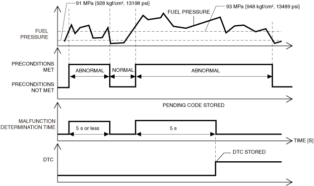
•  Fuel pressure measured by high fuel pressure sensor is 93 MPa {948 kgf/cm2, 13489 psi} or more (hysteresis: 2 MPa {20 kgf/cm2, 290 psi}) for a continuous 5 s.
Preconditions
•  Battery voltage: 8.0 V or more*1
•  Engine speed: 500 rpm or more
•  The following DTC is not detected:
―  Fuel pressure: P0087:00, P0088:00, P0192:00 or P0193:00
―  High pressure fuel pump: P0091:00 or P0092:00
*1: Standard can be verified by displaying PIDs using M-MDS
Malfunction determination period
•  5 s period
Drive cycle
•  1
Self test type
•  CMDTC self test, KOEO self test, KOER self test
Sensor used
•  High fuel pressure sensor
Fail-safe function
•  Performs fuel-cut control.
Vehicle status when DTCs are output
•  Fuel-cut control is performed until the negative battery terminal is disconnected and the engine is stopped.
Possible cause
•  High pressure fuel pump malfunction
•  High fuel pressure sensor malfunction
•  PCM malfunction
System wiring diagram
•  Not applicable
Connector diagram
•  Not applicable


Function Explanation (DTC Detection Outline)

•  The PCM calculates the target fuel pressure appropriate to the engine conditions relative to the actual fuel pressure based on the fuel pressure sensor signal, and provides feedback to the high pressure fuel pump control.
If the actual fuel pressure exceeds the specification, the PCM determines a malfunction in the high pressure fuel pump system, and stores a DTC.
The PCM starts the malfunction determination when the fuel pressure measured by the high fuel pressure sensor is 93 MPa {948 kgf/cm2, 13489 psi} or more, and continues the malfunction determination until the fuel pressure decreases to 91 MPa {928 kgf/cm2, 13198 psi} or less.
am3zzw00036300

Repeatability Verification Procedure

1.  Start the engine and warm it up completely.

PID Item/Simulation Item Used In Diagnosis

PID/DATA monitor item table

PIDs

Reference

FUEL_PRES


Function Inspection Using M-MDS

Step

Inspection

Results

Action

1
PURPOSE: RECORD VEHICLE STATUS WHEN DTC WAS DETECTED TO UTILIZE WITH REPEATABILITY VERIFICATION
•  Record the freeze frame data/snapshot data.
Note
•  Recording can be facilitated using the screen capture function of the PC.
Go to the next step.
2
PURPOSE: INSPECT FOR OTHER RELATED DTCs
•  Perform the DTC inspection for the PCM.
•  Are any other DTCs displayed?
Yes
Repair the malfunctioning location according to the applicable DTC troubleshooting.
Go to the next step.
No
Go to the next step.
3
PURPOSE: VERIFY CONNECTOR CONNECTIONS
•  Start the engine.
•  Access the FUEL_PRES PID using the M-MDS.
•  Does the PID value fluctuate when the following connectors are shaken?
―  High fuel pressure sensor
―  PCM
Yes
Repair or replace the applicable wiring harness or connector parts.
Go to Troubleshooting Diagnostic Procedure to perform the repair completion verification.
No
Go to Troubleshooting Diagnostic Procedure to perform the procedure from Step 1.


Troubleshooting Diagnostic Procedure

Intention of troubleshooting procedure
•  Step 1
―  Perform a unit inspection of the high pressure fuel pump.
•  Step 2
―  Perform a unit inspection of the high fuel pressure sensor.
•  Repair completion verification
―  Verify that the primary malfunction is resolved and there are no other malfunctions.

Step

Inspection

Results

Action

1
PURPOSE: INSPECT HIGH PRESSURE FUEL PUMP FOR MALFUNCTION
•  Inspect the applicable part.
•  Is the part normal?
Yes
Go to the next step.
No
Repair or replace the malfunctioning location and perform the repair completion verification.
2
PURPOSE: INSPECT HIGH FUEL PRESSURE SENSOR FOR MALFUNCTION
•  Inspect the applicable part.
•  Is the part normal?
Yes
Go to the next step.
No
Repair or replace the malfunctioning location and perform the repair completion verification.
Repair completion verification 1
PURPOSE: VERIFY THAT VEHICLE IS REPAIREDPURPOSE: VERIFY THAT VEHICLE IS REPAIRED
•  Install/connect the part removed/disconnected during the troubleshooting procedure.
•  Clear the DTC recorded in the memory.
•  Replicate the vehicle conditions at the time the DTC was detected using the following procedure.
―  Implement the repeatability verification procedure.
•  Perform the DTC inspection for the PCM.
•  Is the same Pending DTC present?
Yes
Refer to the controller area network (CAN) malfunction diagnosis flow to inspect for a CAN communication error.
If the CAN communication is normal, perform the diagnosis from Step 1.
•  If the malfunction recurs, replace the PCM, then go to the next step.
No
Go to the next step.
Repair completion verification 2
PURPOSE: VERIFY IF OTHER DTCs DISPLAYED
•  Perform the DTC inspection.
•  Are any other DTCs displayed?
Yes
Repair the malfunctioning location according to the applicable DTC troubleshooting.
No
DTC troubleshooting completed.