DTC P049D:00 [PCM (SKYACTIV-X)]
DTC P049D:00 [PCM (SKYACTIV-X)]
id0102u9203100
-
Note
-
• To determine the malfunctioning part, proceed with the diagnostics from "Function Inspection Using M-MDS".
Details On DTCs
|
Description
|
EGR valve system: Fully-closed learning error
|
|
Detection condition
|
Determination conditions
|
• The following conditions are met:.
-
― The voltage of the EGR valve position sensor fully-closed learning exceeds the specified range.
― The EGR valve position sensor fully-closed learning is not completed normally.
|
|
Preconditions
|
• Battery voltage: 8 V or more*1
*1: Standard can be verified by displaying PIDs using M-MDS
|
|
Drive cycle
|
• 2
|
|
Self test type
|
• CMDTC self test, KOEO self test, KOER self test
|
|
Sensor used
|
• EGR valve position sensor
|
|
Fail-safe function
|
• Inhibits the EGR control.
|
|
Vehicle status when DTCs are output
|
• Not applicable
|
|
Possible cause
|
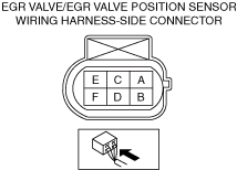
• EGR valve/EGR valve position sensor connector or terminals malfunction
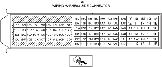
• PCM connector or terminals malfunction
• Open circuit in EGR valve control circuit
• EGR valve malfunction
• EGR valve position sensor malfunction
• PCM malfunction
|
 |
 |
 |
Function Explanation (DTC Detection Outline)
• The PCM learns the standard of the EGR valve position sensor, when fully-closed, when it commands the EGR valve to fully close.
• If the learning value is excessively large or small, or the learning operation is not performed normally, the PCM stores a DTC.
Repeatability Verification Procedure
1. Switch the ignition ON (engine off or on) and wait for 30 s.
2. Switch the ignition OFF and wait for 30 s.
PID Item/Simulation Item Used In Diagnosis
PID/DATA monitor item table
Simulation item table
|
Simulation items
|
Reference
|
|
EGR_COMD
|
|
Function Inspection Using M-MDS
|
Step
|
Inspection
|
Results
|
Action
|
|
1
|
PURPOSE: VERIFY RELATED REPAIR INFORMATION OR SERVICE INFORMATION AVAILABILITY
• Verify related Service Bulletins, on-line repair information, or Service Information availability.
• Is any related Information available?
|
Yes
|
Perform repair or diagnosis according to the available information.
• If the vehicle is not repaired, go to the next step.
|
|
No
|
Go to the next step.
|
|
2
|
PURPOSE: IDENTIFY TRIGGER DTC FOR FREEZE FRAME DATA
• Is the DTC P049D:00 on freeze frame data?
|
Yes
|
Go to the next step.
|
|
No
|
Repair the malfunctioning location according to the applicable DTC troubleshooting.
Go to the next step.
|
|
3
|
PURPOSE: RECORD VEHICLE STATUS WHEN DTC WAS DETECTED TO UTILIZE WITH REPEATABILITY VERIFICATION
• Record the freeze frame data/snapshot data.
-
Note
-
• Recording can be facilitated using the screen capture function of the PC.
|
—
|
Go to Troubleshooting Diagnostic Procedure to perform the procedure from Step 1.
|
|
4
|
PURPOSE: VERIFY CONFORMITY OF EGR VALVE
• Start the engine and idle it.
• Access the following PIDs and simulation item using the M-MDS:
PIDs
-
― EGR_ACT
Simulation item
-
― EGR_COMD
• Perform the following:
-
― Change the simulation item EGR_COMD between 0% and 100%.
― Verify that the PID EGR_ACT monitor value conforms to the simulation item EGR_COMD.
• Does the monitor value of the PID item EGR_ACT conform to the EGR_COMD monitor value?
|
Yes
|
Go to the next step.
|
|
No
|
Go to Troubleshooting Diagnostic Procedure to perform the procedure from Step 1.
|
|
5
|
PURPOSE: VERIFY CONNECTOR CONNECTIONS
• Access the following PIDs using the M-MDS:
PCM
-
― EGR_ACT
• Does the PID value fluctuate when the following connectors are shaken?
-
― EGR valve/EGR valve position sensor
― PCM
|
Yes
|
Inspect the related wiring harness and connector.
• Repair or replace the malfunctioning part.
Go to Troubleshooting Diagnostic Procedure to perform the repair completion verification.
|
|
No
|
Go to Troubleshooting Diagnostic Procedure to perform the procedure from Step 1.
|
Troubleshooting Diagnostic Procedure
Intention of troubleshooting procedure
• Step 1
-
― Perform an inspection of the wiring harnesses between the EGR valve and the PCM.
• Step 2
-
― Perform a unit inspection of the EGR valve.
• Repair completion verification
-
― Verify that the primary malfunction is resolved and there are no other malfunctions.
|
Step
|
Inspection
|
Results
|
Action
|
|
1
|
PURPOSE: INSPECT EGR VALVE CONTROL CIRCUIT FOR OPEN CIRCUIT
• Inspect the applicable circuit for open circuit.
• Is the circuit normal?
|
Yes
|
Go to the next step.
|
|
No
|
Repair or replace the malfunctioning location and perform the repair completion verification.
|
|
2
|
PURPOSE: INSPECT EGR VALVE FOR MALFUNCTION
• Inspect the applicable part.
• Is the part normal?
|
Yes
|
Go to the next step.
|
|
No
|
Repair or replace the malfunctioning location and perform the repair completion verification.
|
|
Repair completion verification 1
|
PURPOSE: VERIFY THAT VEHICLE IS REPAIRED
• Install/connect the part removed/disconnected during the troubleshooting procedure.
• Clear the DTC recorded in the memory.
• Replicate the vehicle conditions at the time the DTC was detected using the following procedure.
-
― Implement the repeatability verification procedure.
• Perform the DTC inspection for the PCM.
• Is the same Pending DTC present?
|
Yes
|
Refer to the controller area network (CAN) malfunction diagnosis flow to inspect for a CAN communication error.
If the CAN communication is normal, perform the diagnosis from Step 1.
• If the malfunction recurs, replace the PCM, then go to the next step.
|
|
No
|
Go to the next step.
|
|
Repair completion verification 2
|
PURPOSE: VERIFY IF OTHER DTCs DISPLAYED
• Perform the DTC inspection.
• Are any other DTCs displayed?
|
Yes
|
Repair the malfunctioning location according to the applicable DTC troubleshooting.
|
|
No
|
DTC troubleshooting completed.
|