• To determine the malfunctioning part, proceed with the diagnostics from “Function Inspection Using M-MDS”.
Details On DTCs
Description
Air bypass valve control circuit range/performance problem
Detection condition
Determination conditions
• When the air bypass valve is not energized, the speed at which the valve returns from the open position to the fully-closed position is extremely slow.
Preconditions
• The following DTCs are not detected:
― P0033:00, P0039:00, P2BBC:00 and P2BBD:00
Drive cycle
• 1
Self test type
• CMDTC self test
Sensor used
• Air bypass valve position sensor
Fail-safe function
• Inhibits the boost system.
• Stops the EGR control.
Vehicle status when DTCs are output
• Not applicable
Possible cause
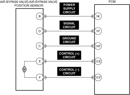
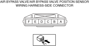
• Air bypass valve/air bypass valve position sensor connectors or terminals malfunction
• PCM connector or terminals malfunction
• Short to ground in any of the following air bypass valve/air bypass valve position sensor circuits.
― Power supply circuit
― Signal circuit
― Control (+) circuit
― Control (−) circuit
• Short to power supply in any of the following air bypass valve/air bypass valve position sensor circuits.
― Signal circuit
― Ground circuit
― Control (+) circuit
― Control (−) circuit
• Open circuit in any of the following air bypass valve/air bypass valve position sensor circuits.
― Power supply circuit
― Signal circuit
― Ground circuit
― Control (+) circuit
― Control (−) circuit
• Air bypass valve position sensor malfunction
• Air bypass valve malfunction
• PCM malfunction
Function Explanation (DTC Detection Outline)
• The internal structure of the air bypass valve is designed so that the valve returns to the fully-closed position when the air bypass valve is not energized.
If the speed at which the air bypass valve returns from the open position to the fully-closed position is extremely slow when the air bypass valve energization is turned off, the PCM determines a malfunction in the air bypass valve and stores a DTC.
Repeatability Verification Procedure
1. Warm up the engine to allow the engine coolant temperature to reach 80 °C {176 °F} or more.
• Does the PID value fluctuate when the following connectors are shaken?
― Air bypass valve position sensor
― PCM
Yes
Inspect the related wiring harness and connector.
• Repair or replace the malfunctioning part.
Go to Troubleshooting Diagnostic Procedure to perform the repair completion verification.
No
Go to Troubleshooting Diagnostic Procedure to perform the procedure from Step 1.
Troubleshooting Diagnostic Procedure
Intention of troubleshooting procedure
• Step 1—3
― Perform an inspection of the connectors and wiring harnesses between the air bypass valve/air bypass valve position sensor and the PCM.
• Step 4
― Perform a unit inspection of the air bypass valve.
• Step 5
― Perform a unit inspection of the air bypass valve position sensor.
• Repair completion verification
― Verify that the primary malfunction is resolved and there are no other malfunctions.
Step
Inspection
Results
Action
1
PURPOSE: INSPECT AIR BYPASS VALVE/AIR BYPASS VALVE POSITION SENSOR POWER SUPPLY CIRCUIT AND SIGNAL CIRCUIT AND CONTROL (+) CIRCUIT AND CONTROL (−) CIRCUIT FOR SHORT TO GROUND
• Inspect the applicable circuit for a short to ground.
Repair or replace the malfunctioning location and perform the repair completion verification.
2
PURPOSE: INSPECT AIR BYPASS VALVE/AIR BYPASS VALVE POSITION SENSOR SIGNAL CIRCUIT AND GROUND CIRCUIT AND CONTROL (+) CIRCUIT AND CONTROL (−) CIRCUIT FOR SHORT TO POWER SUPPLY
• Inspect the applicable circuit for a short to power supply.
Repair or replace the malfunctioning location and perform the repair completion verification.
3
PURPOSE: INSPECT AIR BYPASS VALVE/AIR BYPASS VALVE POSITION SENSOR POWER SUPPLY CIRCUIT AND SIGNAL CIRCUIT AND GROUND CIRCUIT AND CONTROL (+) CIRCUIT AND CONTROL (−) CIRCUIT FOR OPEN CIRCUIT
• Inspect the applicable circuit for open circuit.