Home

Mazdamanuals.com

DTC P2504:00 [PCM (SKYACTIV-X)]

DTC P2504:00 [PCM (SKYACTIV-X)]


 id0102u9709700

Note
•  To determine the malfunctioning part, proceed with the diagnostics from "Function Inspection Using M-MDS".

Details On DTCs

Description

Generator system: Voltage high input

Detection condition
Determination conditions
•  If any of the following conditions is met:
Condition A
―  Battery voltage is 15.9 V or more for a continuous specified time.
Condition B
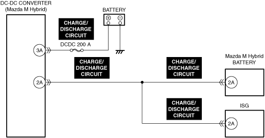
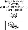
―  DC-DC converter (Mazda M Hybrid) input voltage (terminal 2A) is 35 V or more for a continuous specified time.
Condition C
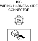
―  Voltage of integrated starter generator (ISG) terminal 2A is 35 V or more for a continuous specified time.
Condition D
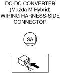
―  DC-DC converter (Mazda M Hybrid) output voltage (terminal 3A) is 16 V or more for a continuous specified time.
Preconditions
•  Contactor for Mazda M Hybrid battery is on.
Malfunction determination period
•  5 s period
Drive cycle
•  1
Self test type
•  CMDTC self test
Sensor used
•  PCM
•  DC-DC converter (Mazda M Hybrid)
•  Mazda M Hybrid battery
•  Integrated starter generator (ISG)
Fail-safe function
•  Stops power supply by step-down circuit in DC-DC converter (Mazda M Hybrid).
•  Stops power generation by integrated starter generator (ISG).
•  Turns off contactor for Mazda M Hybrid battery and supply power to vehicle electrical devices (12 V power supply) from battery.
Vehicle status when DTCs are output
•  If the vehicle continues to be driven while the DTC is detected the battery will be depleted.
―  A malfunction occurs with an electrical device and the vehicle stops.
•  The following vehicle conditions differ depending on the type of malfunction:
―  Vehicle shock may occur due to generator load.
―  Idling feel due to generator-stop may occur.
Possible cause
•  Poor connection of the following parts:
―  DC-DC converter (Mazda M Hybrid)
―  Mazda M Hybrid battery
―  Integrated starter generator (ISG)
•  Connector or terminal malfunction of the following parts:
―  DC-DC converter (Mazda M Hybrid)
―  Mazda M Hybrid battery
―  Integrated starter generator (ISG)
•  Charge/discharge circuits are short to each other
•  PCM malfunction


Function Explanation (DTC Detection Outline)

•  The PCM determines that a malfunction occurred based on high voltage of each charging system, and safety assurance is performed.

Repeatability Verification Procedure

1.  Clear the DTC from the PCM memory using the M-MDS. (See CLEARING DTC.)
2.  Start the engine.
3.  Try to reproduce the malfunction by driving the vehicle for 10 s based on the values in the freeze frame data/snapshot data.

PID Item/Simulation Item Used In Diagnosis

•  Not applicable

Function Inspection Using M-MDS

Step

Inspection

Results

Action

1
PURPOSE: VERIFY RELATED REPAIR INFORMATION OR SERVICE INFORMATION AVAILABILITY
•  Verify related Service Bulletins, on-line repair information, or Service Information availability.
•  Is any related Information available?
Yes
Perform repair or diagnosis according to the available information.
•  If the vehicle is not repaired, go to the next step.
No
Go to the next step.
2
PURPOSE: RECORD VEHICLE STATUS WHEN DTC WAS DETECTED TO UTILIZE WITH REPEATABILITY VERIFICATION
•  Record the freeze frame data/snapshot data.
Note
•  Recording can be facilitated using the screen capture function of the PC.
Go to the next step.
3
PURPOSE: INSPECT FOR OTHER RELATED DTCs
•  Perform the DTC inspection for the following modules.
―  Integrated starter generator (ISG)
―  Mazda M Hybrid battery
―  DC-DC converter (Mazda M Hybrid)
•  Are any DTCs displayed?
Yes
Repair the malfunctioning location according to the applicable DTC troubleshooting.
No
Go to the next step.
4
PURPOSE: INSPECT FOR OTHER RELATED DTCs
•  Perform the DTC inspection for the PCM.
•  Are any other of the following DTCs displayed?
―  P0AB9:00
―  P2502:00
―  P2503:00
Yes
Repair the malfunctioning location according to the applicable DTC troubleshooting.
No
Go to Troubleshooting Diagnostic Procedure to perform the procedure from Step 1.


Troubleshooting Diagnostic Procedure

Intention of troubleshooting procedure
•  Step 1
―  Perform an inspection of the DC-DC converter (Mazda M Hybrid).
•  Step 2—3
―  Perform an inspection of the DC-DC converter (Mazda M Hybrid) connector.
•  Step 4—5
―  Perform an inspection of the Mazda M Hybrid battery connector.
•  Step 6—7
―  Perform an inspection of the integrated starter generator (ISG) connector.
•  Step 8
―  Perform an inspection of charge/discharge circuits for short to each other.
•  Repair completion verification
―  Verify that the primary malfunction is resolved and there are no other malfunctions.

Step

Inspection

Results

Action

1
DETERMINE IF MALFUNCTION CAUSE IS SHORT TO EACH OTHER IN CHARGE/DISCHARGE CIRCUITS OR OTHER PART
•  Measure the voltage between the DC-DC converter (Mazda M Hybrid) terminal 3A (wiring harness-side) and battery positive terminal.
•  Is the voltage 15.9 V or more?
Yes
Go to the next step.
No
Intermittent concern exists.
•  Perform the repair completion verification.
2
PURPOSE: VERIFY IF POOR CONNECTION OF DC-DC CONVERTER (Mazda M Hybrid) AFFECTS DIAGNOSTIC RESULTS
•  Inspect the connection condition (part installation condition, connector connection condition) for the DC-DC converter (Mazda M Hybrid).
•  Is the connection condition (part installation condition, connector connection condition) for each part normal?
Yes
Go to the next step.
No
Connect each part or the connector correctly, then go to Step 9.
3
PURPOSE: INSPECT DC-DC CONVERTER (Mazda M Hybrid) CONNECTOR FOR MALFUNCTION
•  Inspect the applicable connector and terminal.
•  Are the connector and terminal normal?
Yes
Go to the next step.
No
Repair or replace the malfunctioning location, then go to Step 9.
4
PURPOSE: VERIFY IF POOR CONNECTION OF Mazda M Hybrid BATTERY AFFECTS DIAGNOSTIC RESULTS
•  Inspect the connection condition (part installation condition, connector connection condition) for the Mazda M Hybrid battery.
•  Is the connection condition (part installation condition, connector connection condition) for each part normal?
Yes
Go to the next step.
No
Connect each part or the connector correctly, then go to Step 9.
5
PURPOSE: INSPECT Mazda M Hybrid BATTERY CONNECTOR FOR MALFUNCTION
•  Inspect the applicable connector and terminal.
•  Are the connector and terminal normal?
Yes
Go to the next step.
No
Repair or replace the malfunctioning location, then go to Step 9.
6
PURPOSE: VERIFY IF POOR CONNECTION OF INTEGRATED STARTER GENERATOR (ISG) AFFECTS DIAGNOSTIC RESULTS
•  Inspect the connection condition (part installation condition, connector connection condition) for the integrated starter generator (ISG).
•  Is the connection condition (part installation condition, connector connection condition) for each part normal?
Yes
Go to the next step.
No
Connect each part or the connector correctly, then go to Step 9.
7
PURPOSE: INSPECT INTEGRATED STARTER GENERATOR (ISG) CONNECTOR FOR MALFUNCTION
•  Inspect the applicable connector and terminal.
•  Are the connector and terminal normal?
Yes
Go to the next step.
No
Repair or replace the malfunctioning location, then go to Step 9.
8
PURPOSE: INSPECT CHARGE/DISCHARGE CIRCUITS FOR SHORT TO EACH OTHER
•  Inspect the charge/discharge circuits for a short to each other.
•  Is the circuit normal?
Yes
Go to the next step.
No
Repair or replace the malfunctioning location, then go to the next step.
9
PURPOSE: VERIFY Mazda M Hybrid BATTERY DTCs
•  Perform the DTC inspection for the Mazda M Hybrid battery.
•  Are any other DTCs displayed?
Yes
Repair the malfunctioning location according to the applicable DTC troubleshooting.
No
Perform the repair completion verification.
Repair completion verification 1
PURPOSE: VERIFY THAT VEHICLE IS REPAIRED
•  Install/connect the part removed/disconnected during the troubleshooting procedure.
•  Clear the DTC recorded in the memory.
•  Replicate the vehicle conditions at the time the DTC was detected using the following procedure.
―  Implement the repeatability verification procedure.
•  Perform the DTC inspection for the PCM.
•  Is the same Pending DTC present?
Yes
Refer to the controller area network (CAN) malfunction diagnosis flow to inspect for a CAN communication error.
If the CAN communication is normal, perform the diagnosis from Step 1.
•  If the malfunction recurs, replace the PCM, then go to the next step.
No
Go to the next step.
Repair completion verification 2
PURPOSE: VERIFY IF OTHER DTCs DISPLAYED
•  Perform the DTC inspection.
•  Are any other DTCs displayed?
Yes
Repair the malfunctioning location according to the applicable DTC troubleshooting.
No
DTC troubleshooting completed.